by Dr. Min Zhang, the EMC Consultant
Most of the noise that engineers come across in the field is generated by high-frequency, fast switching devices. Typical examples are motor drive inverters, DC-DC converters, power supplies, microcontrollers and communication chips. Therefore, filters are often designed to suppress the noise caused by switching events.
In the past, IGBTs and MOSFETs were the main switches. MOSFETs were predominantly used in low voltage applications while IGBTs were used in medium voltage applications. When the voltage is above 800V, IGCTs and GTOs are the devices of choice. MOSFETs can be switched rather quickly, but they are limited by the voltage rating and their thermal properties, therefore, typically they are limited to about 150kHz switching frequency and the rise time is often found to be from a few nanoseconds to 10s of nanoseconds. IGBTs have a tail-current, which limits their switching speed and switching frequency. Typically, the switching frequency of an IGBT based system is limited to about 60kHz.
This will soon change as the newly developed wide-band-gap (WBG) devices such as Silicon-carbide (SiC) and Gallium-nitride (GaN) devices show superior performance over the MOSFETs and IGBTs. The fact that they can switch faster at higher voltage means the dV/dt of WBG devices is a lot higher. This inevitably leads to more EMI.
There are two aspects of a switching event, the switching frequency and the switching speed. When talking about EMI associated with the switching events, many engineers often focus on the switching frequency and overlook the impact of switching speed. The switching speed should have more attention paid to as it is the main EMI source. It is not necessary to have a high switching frequency to cause EMI problems. Consider this example; an electrostatic discharge (ESD) event does not have MHz of switching frequency, but the rise time is as short as 10s-100s of picoseconds. One ESD event could potentially radiate the energy to a nearby system and cause trouble.
A switching event is simulated in the SPICE simulation software. The simulated switching event has a 60kHz switching frequency, with 600V DC voltage, and the duty ratio in this case is 50%. The rise time is set as 12 ns to give a 5V/ns switching speed. Spectrum analysis of the switching event is shown in Figure 1.
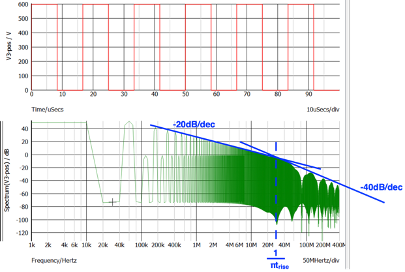
Notice that the -20dB/decade line and the -40dB/decade line crosses at the frequency point of 1/πtrise, which in this case is calculated to be 26.5MHz. Ideally, one would like the -40dB/decade roll off to occur at a lower frequency point, because the noise spectrum decreases a lot faster after this crossing point. But the roll off point only depends on the rise time of a switching event.
Engineers often don’t have the option of shifting this point. This is because the rise time of a switching event often cannot be increased as increased rise time leads to more switching loss and less system efficiency.
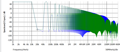
To demonstrate the effect of sharp rise time, in Figure 2, a faster rise time (10V/ns) is simulated for comparison. As it can be seen, every time the switching speed is doubled, it results in a 3-6dB noise increase from 1/πtrise.
Once the spectrum characteristics of a switching event are understood, it is then easy to design a filter that aims to suppress the noise at the frequency range of interests.
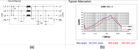
For instance, a motor drive causes conducted emission between 100 kHz to 10 MHz, the lower frequency range noise (<1MHz) often needs differential mode filtering, whereas, between 1MHz and 10 MHz, some form of common-mode filtering is needed. A three-phase filter that has sufficient attenuation in this range would be a good choice. One example is a C-L-C (π) filter, which is shown in Figure 3.
Training
If you want to learn more about EMC and become an expert in troubleshooting EMI problems. Why not attend our video training course? Priced from $199, you can get 10 hour lessons. Check https://mach1design-shop.fedevel.education/itemDetail.html?itemtype=course&dbid=1644339825702&instrid=us-east-2_4pKkzzNo1:fe56227a-47c8-4ea8-ba6f-2930d01d7db8