by Dr. Min Zhang, the EMC Consultant
Download link provided
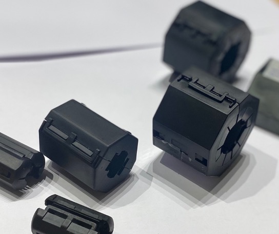
The basic structure of an inductor is simple. Wind an enamelled wire around some magnetic core material will give you an inductor. But there are many different types of magnetic core material such as ferrite, powdered iron. The shape of the core can be toroid, E-shape and many more. The winding can be a single strand conductor, or multi-strand (rope-type) winding, or even a Litz wire. Engineers should select the right choice of inductor for their specific applications.
For example, nanocrystalline materials have become popular for inductor/common mode choke due to their performance in the broadband spectrum. But for motor drive application or high power switched mode power supply (SMPS) application, where EMI issue often starts with a few kHz, Manganese-Zinc or iron-powdered core is a better choice.
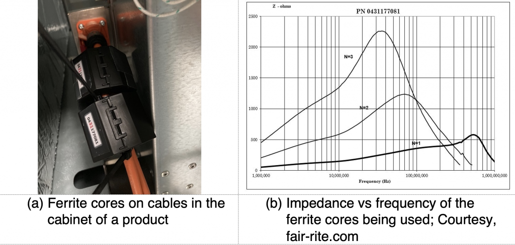
If you increase the number of turns of an inductor’s winding, you would expect the inductance value increase. In fact, you would expect the inductance value increase a lot since the relationship between the inductance and the number of turns is defined in Eq. 1. As it can be seen, the inductance is proportional to the n2.
L=n2Akμ0 (Eq.1)
where n is the number of turns of a winding, A is the cross-section area, k relates to the geometry of the coil of an inductor, μ0 is the permeability of free space.
In reality, however, this is often not the case. As the number of turns increases, so is the turn-to-turn capacitance of the winding. Increased turn-to-turn capacitance shifts the resonant frequency of an inductor to a lower frequency point, meaning the capacitance part of an inductor starts to dominate. In fact, this is one of the main reasons that engineers sometimes find an inductor/common mode choke (CMC) shows little impact in a design.
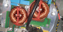
A case study is presented here to demonstrate the point we made. In Figure 1, a two-stage filter featuring two CMCs was designed to suppress noise in the frequency range of 20 to 30 MHz. The datasheet of the CMCs suggests good attenuation in the frequency range of interest, however, when the circuit was tested, engineers found the filter didn’t suppress the noise as they had hoped. The CMC is a nanocrystalline core with a ‘rope’ type winding structure. The first suggestion we made is to remove the two CMCs from the circuit and re-tested the board EMC performance.
To the engineers’ surprise, removing the CMCs improved the noise performance in the frequency range between 20 and 30 MHz by at least 6 dB. In the lower frequency range between 150kHz and 1 MHz, however, the noise performance was getting worse. We didn’t have the test result in hand, but for demonstration purposes, see below
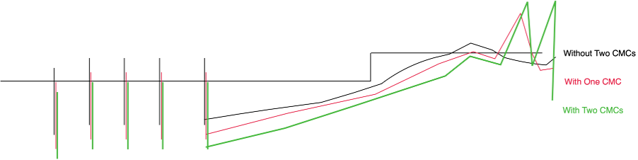
It is not a surprise that the CMCs didn’t work in the designed frequency range, as from 20 MHz, the winding capacitance due to the structure of this CMC dominates. In the lower frequency range, the leakage inductance of the CMC has an impact, this explains why removing the CMCs, the lower frequency EMC performance was getting worse.
Changing the two CMCs to a ferrite core with less turns of winding solved the problem.
Skin effect, eddy current and proximity effect are all related to frequency. As frequency increases, RF current tends to travel on the very outer thin layer of a conductor, hence the name ‘skin effect’. Engineers should be aware that these effects not only significantly increase the loss of an inductor, they also have an impact on the EMC performance.