The TEM Cell unit we used is Tekbox TBTC-3, a large TEM cell compared with other TEM cells. This TEM cell has a spectrum height of 15cm, which is suitable for many units, especially PCBs.
The TEM Cell is located inside an EMC shielding tent, this is desirable as for radiated emissions, an open TEM Cell will pick up ambient noise.
The effective area inside the TEM cell is defined by the standard, the DUT needs to be placed inside the defined area within the TEM Cell.
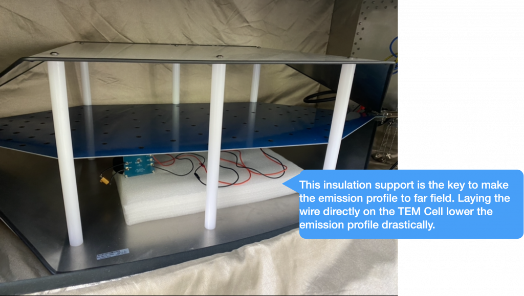
The insulation support is very important, here, we used 5cm tall insulation support and we made sure that the wires are placed on the insulation support.
The wire length is chosen to be more or less the same as what the standard defines, i.e. in this case, between 1.5 and 2m. However, due to the constraint of the space, the wires are meandered, this would affect the radiation profile.
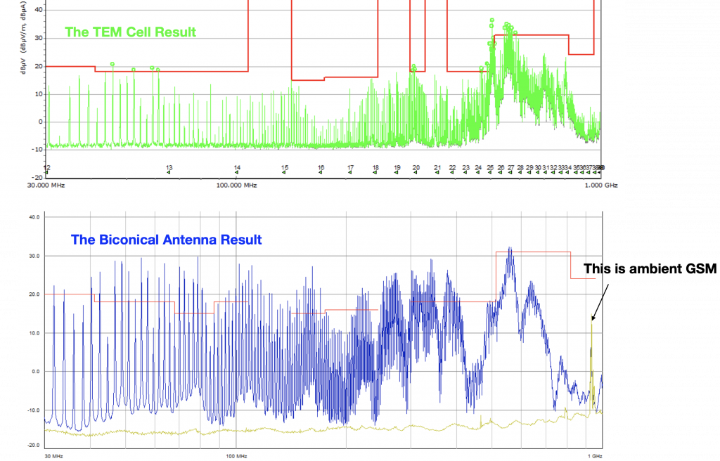
The following diagrams compared the TEM Cell results with that of the far field measurement (according to CISPR 25, 1 meter antenna location to the DUT).
A second DUT is tested.
Second DUT tested in the TEM Cell
The comparison results are shown below.
The TEM Cell result shows a very similar radiated emission profile with the comparison of antenna far field result, the noise level in the lower frequency range shows about 8 dB less
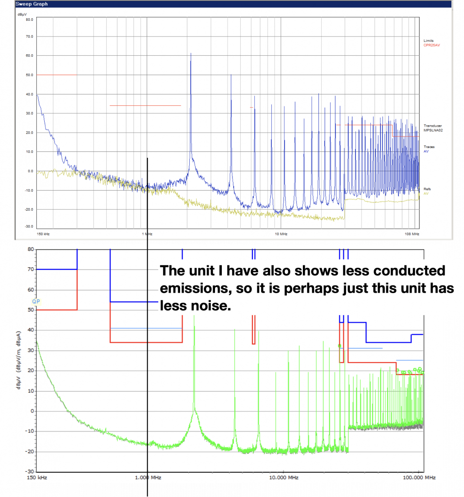
This might be explained by the fact that the DUT has also less conducted noise compared with the benchmark unit. See below:
Conducted emission results between the DUT and the benchmark unit
If the conducted emission level in the DUT is 8 dB less, it explains why the radiated emission level of the DUT is also lower than the benchmark unit.
Overall, the TEM Cell result shows a very similar noise profile compared with the far field measurement. We are confident to use this method as a pre-compliance test set-up.
Grounding and shielding has always been a challenging issue when it comes to large system installations. Even the most experienced engineers in prestigious companies often get the system installation wrong, intentionally or unintentionally.
In this article, we discuss the grounding and shielding techniques using a practical case study. In this case, the system under the discussion is an instrumentation system used for a space project. The ground loop created by the ground wires lead to loop issues, several solutions are discussed to address this issue.
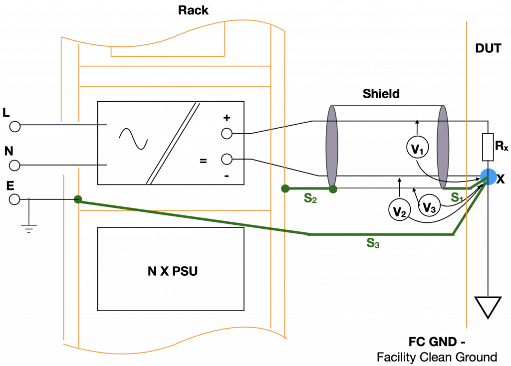
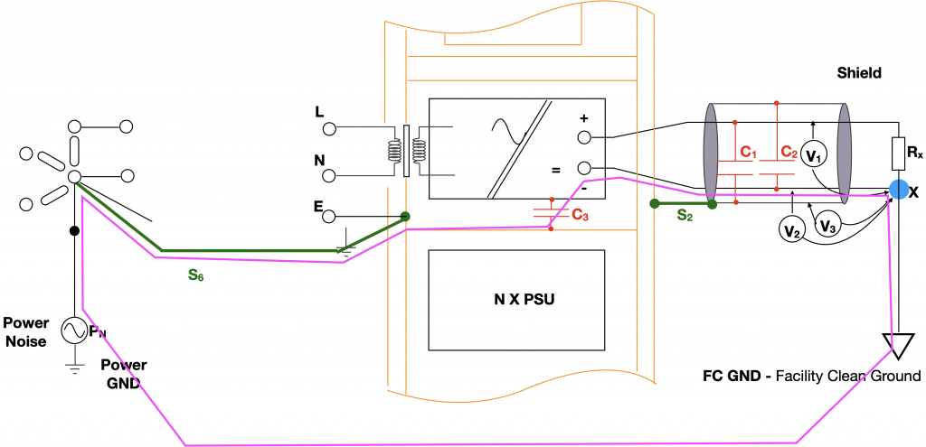
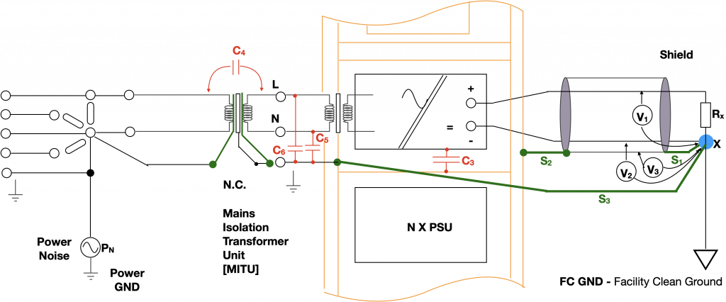
The system
For demonstration purposes, we can treat the DUT as a pure resistive load, the signal needs to be measured is the voltage across the receiving load RX. The load is ‘grounded’ to the facility clean ground. Note that there is an X symbol at the bottom of the RX, the X symbol represents the ‘star’ point, a reference point often used in space application (As a satellite floats in the space, there cannot a ‘ground’ point, hence the ‘star’ point from historical reasons).
For minimal noise voltage received by RX, all three conductors (DC+ line, DC- line and the shield) should ideally have zero RF voltage difference with regards to the ‘star’ point X. Wire bonding strap S1 and S2 are crucial to ‘close the field’ inside the shield. It has been found that the shield also needs to be connected to the ‘star’ point via a ground wire strap S3 to ensure V3=0.
The Instrumentation System
Noise introduced by the Ground Loop
Due to the parasitic capacitance between the V+ and the inner shield (C1) and the parasitic capacitance between the V- and the inner shield (C2), RF noise voltages are developed, therefore V1,2 are not zero. This is particularly true when the connection between the PSU and the EUT is long.
The DUT is powered by tens of DC power supplies, all of which are galvanically isolated from the metal racks. However, the internal assembly of the power supply unit (PSU) represents significant parasitic capacitance C3 with regards to the rack frame, typically 50 nF per unit. In case where the rack frame is connected to the primary power supply ground, the residual noise marked PN of the three-phase current imbalance will be transferred to the DUT line via C3.
Demonstration of a worst-case scenario : Shield end S1 is not connected to the ‘star’ point, ground strap S3 is also disconnected. Rack chassis is earthed to the power ground via ground strap S6.Pink line is the ground loop.
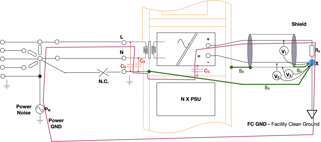
It is easy to break the loop, isn’t it?
It looks easy to break the loop by disconnecting S6. In order to achieve a ‘clean’ break, we also need to make sure the earth wire is cut. Note that special preventions are required to comply with personnel safety requirements. But this disconnection is not a clean break from RF noise point of view. Because the power supply unit has an input filter which includes Y capacitors to earth. These capacitors now provide the noise path as shown below:
Ground loop noise uses the low impedance path provided by C3
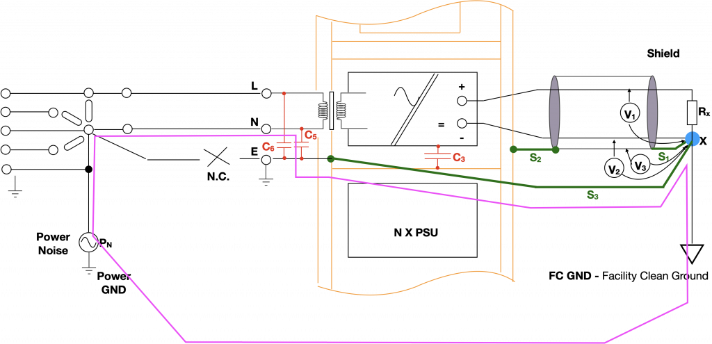
This is another ground loop
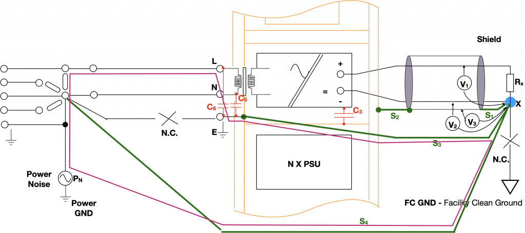
We therefore need to further break the loop, this can be achieved by the following configuration. Breaking the connection between the ‘star’ point and the facility clean ground is the key, because now the ‘star’ point X is the same ground potential as the power ground, so there is a very small potential difference between the two ground points, this will prevent current from using C3. The ground strap S4 is important to achieve minimum potential difference between the two ground points.
The minimum grounding scheme which limits the ground loop current
The proposed solution provides the minimum configuration for such an instrumentation. The grounding scheme can be further improved by the following optimum configuration. The key component in this configuration is the mains isolation transformer unit which consists of two shields. The double shielded transformer is specially made for best attenuation of primary-to-secondary noise transfer, i.e. transfer capacitance C4 is mined to <10nF.
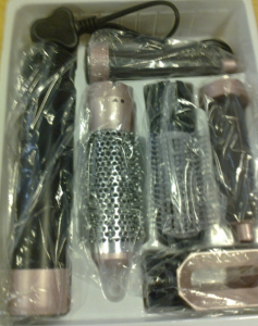
A quick browse on the website, you will find lots of recalled products due to safety failures. Among which, the high voltage (HV) safety failures have taken a large proportion of the total cases. What is more interesting is that the number of the hair care products shown in the list. It is quite concerning if we find a “good hair day” turns into a nightmare due to the safety issues. I have friends who experienced leakage current issue with a counterfeit hair dryer product and I will not be surprised if some of these products could cause fire.
One of the products that have HV safety issues
The products that are forced to be recalled often present serious risks of electric shock. These products often either do not meet the requirements of the Electrical Equipment (Safety) Regulations 2016 or the plugs & Sockets (Safety) Regulations 1994 (BS1363). Some common failure modes are summarised:
Failure to comply with the creepage and clearance requirements (including poor quality soldering).
The wire diameter is too thin, i.e. not rated for the suitable current.
Wrong/no fuse is fitted.
Lack of general safety design, for instance, lack of power interrupting mechanism.
Insufficient insulation.
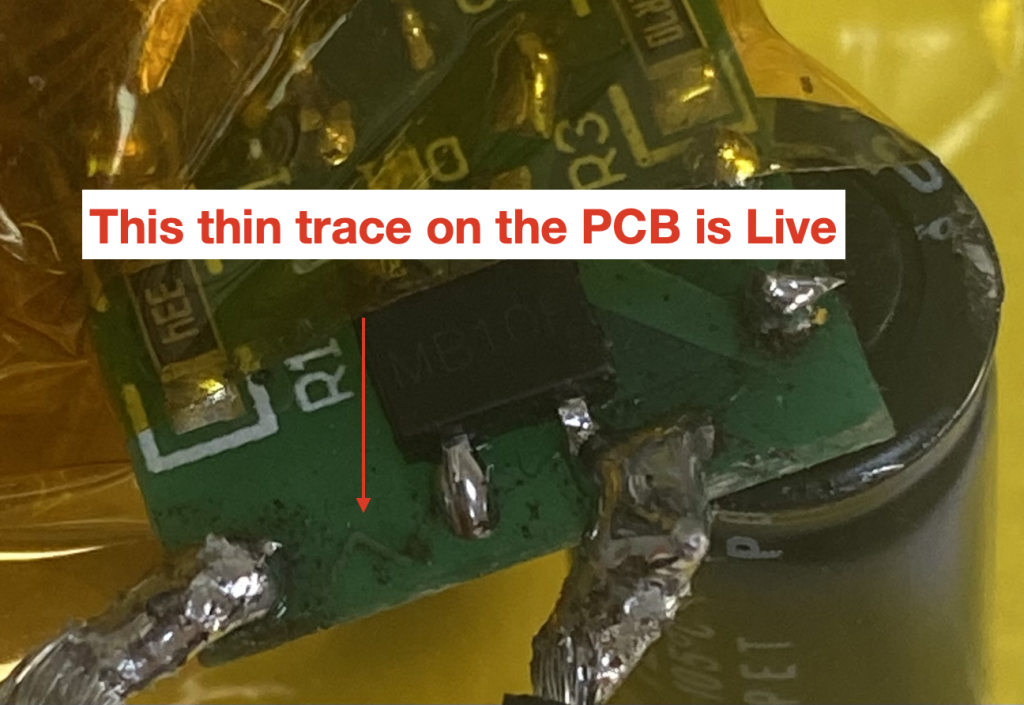
I have seen some HV design in the past which pose serious health and safety hazards
If the safety operation of these products cannot be guaranteed, I cannot imagine if they have done any EMC tests. Yet, some of these products have a CE marking label. We should not allow products like this appear in the market.
Many of these products are imported from Asia into the EU market, and some of them are even sold in big platforms such as Amazon, the Range and TKMAXX. Clearly this shows a sign of lack of expertise in quality control within these organisations.