By Dr. Min Zhang, the EMC Consultant
PDF download
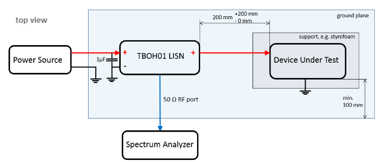
I wrote in the past about how to set up conducted emission pre-compliance EMC test and made videos demonstrations https://youtu.be/KHxbk4eToXs . There are some details regarding to the test set-up. Here I summarised it below:
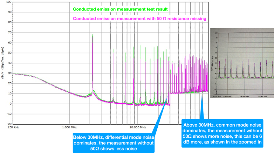
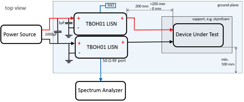
- 50Ω terminations. If two LISNs are used(as what a typical automotive application would be), make sure that one of the unmeasured LISNs (if you are measuring the 12V line, then it is the 0V line LISN) is terminated with a 50Ω resistor. Failing to do so will result in big test error. See below:
2. How important is the 1μF input capacitor to the LISN?
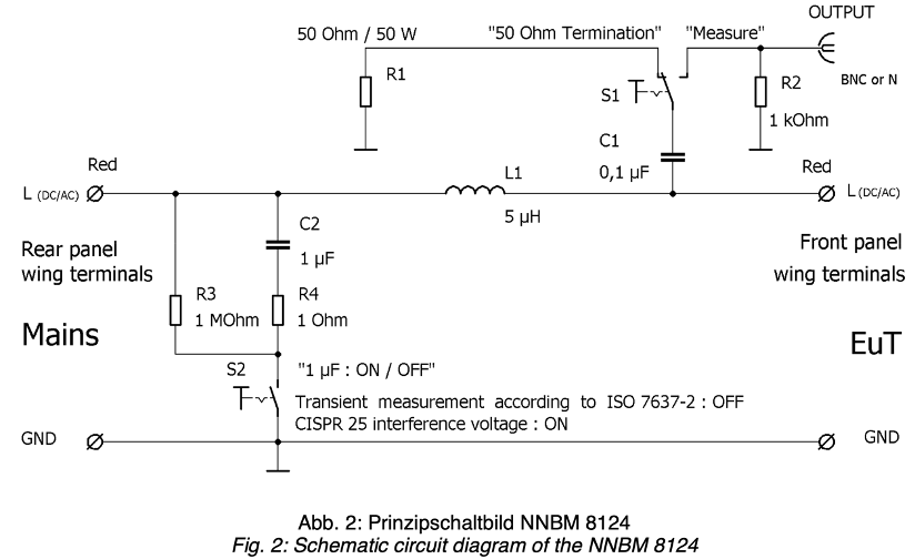
In some of the commercially built LISNs, there’s a switch for switching the 1μF input capacitor, shown in Figure 2. The 1μF input capacitor is used in the conducted emission test, but you have to switch it off if you are doing any kind of transient test, because the capacitor could potentially short the transient.
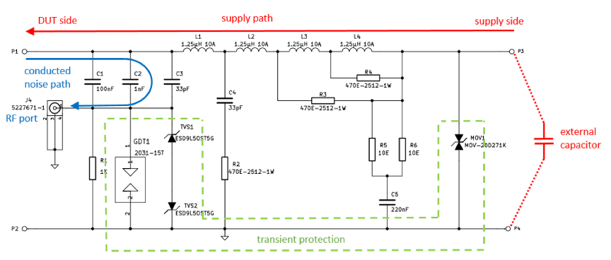
The Texbox LISNs I use don’t have the 1μF input capacitor built in, so it is recommended that the users should fit it themselves, as shown in Figure 3 & Figure 4 [1].
So how important is this 1μF input capacitor for the conducted emission measurement? We consulted Tekbox and here’s what they replied:
“
Looking at the impedance specification of a 5μH LISN – actually I pasted the DO160 spec, because it gives a clearer picture, as it is specified down to 10kHz:

From approximately 3 MHz to 110 MHz, the 5μH inductor has a high impedance and the impedance of the LISN is dominated by the 50 Ohm load impedance at the RF terminal and the capacitor is not relevant. Below 3 MHz, the impedance of the 5μH inductor decreases and in combination with the low impedance of the capacitor, the overall impedance decreases. At approximately 20kHz, the inductor impedance becomes close to zero and the capacitor starts to dominate, as its impedance increases with decreasing frequency.
I made impedance measurements with the 1μF capacitor removed. At approximately 1MHz, the impedance crosses the red limit line and you would start measuring higher spurious levels, compared to what you would measure with the 1μF capacitor.
Consequently, with or without capacitor, above 1 MHz there is no effect on the measurement result. Below 1 MHz, the measured spurious levels will be higher, compared to the correct set up. However, it will never be a lot, as there are always capacitors in the power supply – at 150 kHz it may be approximately 2~3 dB higher, if you have 1-to-2-meter supply cable length.
Interestingly, a customer came up with a similar question, as our wiring diagram seems weird at the first look:
Above 150 kHz, the impedance of the capacitor is pretty low. Consequently, I simply replaced it by a short connection. For the LISN impedance from 150kHz to 110MHz is does not make a difference, whether you have a capacitor or a short at the source side of the LISN. For DO160 a short would be ok as well, as there is no minimum limit for the impedance below 100 kHz. However, the 1μF capacitor needs to be replaced by a 10μF capacitor, in order to avoid crossing the upper impedance limit at very low frequencies.
Replacing the capacitor by a short is also not a violation of CISPR 16, as the standard requires the LISN impedance to be within Limits with both shorted or open source terminals.
In practice, the measurement results of a set up without the 1μF are most likely fine, as long as the supply wires are short. The 5μH inductor mimics a 5m cable harness, typical for the maximum cable length you would have between car battery and an electronic device in a car. In a set-up that sees a 25 cm cable length and have the output capacitors of your power supply providing the low impedance at the source side of the inductor.”
Reference
[1] M. Mayerhofer, “Conducted emission measurement using the Tekbox 5μH LISN TBOH01,” [Online]. Available: https://www.tekbox.com/product/AN_Conducted_Noise_Measurement_Tek boxLISN_TBOH01_EMCview.pdf.
Pingback: Filtering the ambient noise caused by PSU – EMC and Compliance Service Worldwide