By Dr. Min Zhang, the EMC Consultant
PDF download link
There are two common ways of separating common-mode and differential-mode noise. One is the voltage method; the other is the current method.
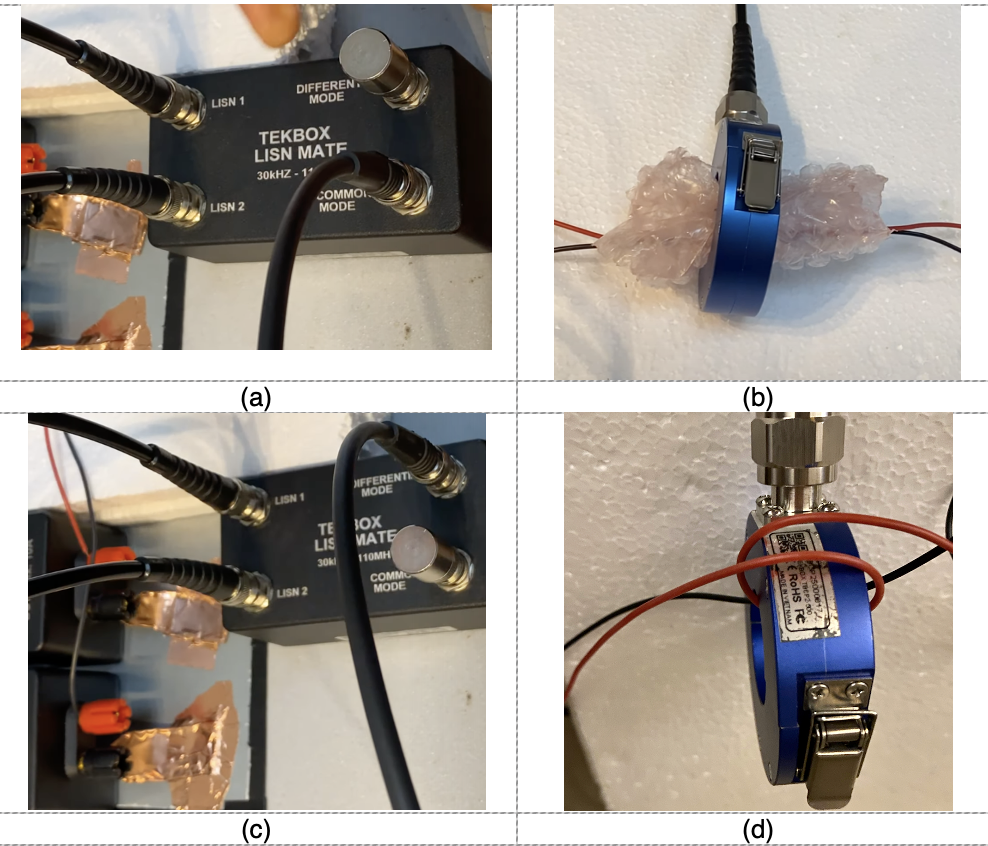
When using voltage method, a LISN-Mate is often used [1] [2] [3]. When using current method, an RF current probe can be configured to measure either common-mode or differential-mode noise depending on the wiring configuration.
I have demonstrated how to set up the test using both methods, see https://youtu.be/0uCXs602_6M. The set-up can be found in Figure 1. This article is a follow-up, which discusses the test results and tries to make sense of it.

We used a buck converter as the DUT and set up the test. The LISN-MATE test result can be found in Figure2.

We then used the current probe method and compared the results with the LISN-mate result. Because current probe measures the current, we need to find a way of converting the results into voltage. This is done in the control software EMCView, where two settings are very important.

The first setting is the Lisn/Att Cor where I selected the transfer impedance file of the current probe I used. The current probe manufacturers should always provide you with the transfer impedance file of the probe you purchase. This file converts the voltage reading of a spectrum analyser to current reading (dBμV to dBμA, as dBμA=dBμV-dBΩ, where dBΩ is the transfer impedance).
The second setting is that I added a 28 dB attenuation compensation. And the reason is:
Both LISNs used for the current probe set-up are terminated with 50Ω resistors. This is important. When I measured IDM using a current probe, I have measured 2×IDM due to the wiring configuration of the current probe on the cable, so I would need to divide the value by 2, or subtract 6dB on the output. The differential voltage is measured on a 50Ω in the LISN voltage set-up, this means I will then need to add 34dBΩ (50Ω) to give me the DM voltage. That means 28dB compensation file in EMC view.
When I measured ICM using a current probe, I also measured 2×ICM according to the picture below, so I also need to subtract 6dB on the output, then add 34dBΩ (50Ω) to give me the CM voltage reading. That means, again, 28dB compensation file in the EMC view.

The comparison between voltage (LISN-MATE) and current measurement are shown in Figure 5 and Figure 6. Note that in order to see the difference more clearly, we turned off the attenuator in the current probe measurement, this results in a lower noise floor.
On the differential-mode noise (Figure 5), from 150kHz to 30MHz both methods are amazingly close (error difference is within 2-3 dB), from 40-100 MHz, the LISN-MATE gives 4-6dB higher reading. But from 30MHz upwards, common-mode noise starts to dominate, there will be CM to DM conversion in the system set-up, so I expected measurement difference between the two in this frequency range.
On the common-mode noise (Figure 6), it is the low frequency range (150kHz to 30MHz) that shows 6-10dB measurement difference. From 30MHz onwards, the noise is predominantly common-mode, therefore the measurement difference in this frequency range is not big.


In summary, both the LISN-MATE and current probe methods can separate differential and common-mode noise well. The differential-mode noise is dominant in the lower frequency range (sub 30MHz), so I tend to trust the differential mode noise results in this region. From 30MHz, noise is predominantly common-mode, so in this frequency range, I tend to trust the common-mode noise results.
Reference
| [1] | H. W. Ott, Electromagnetic Compatibility Engineering, New Jersey: Wiley, 2009. |
| [2] | Tekbox, “LISN-MATE,” [Online]. Available: https://www.tekbox.com/product/TBLM1_LISN_Mate_Manual.pdf. |
| [3] | K. Wyatt, “Review: Tekbox LISN Mate is valuable for evaluating filter circuits,” [Online]. Available: https://www.edn.com/review-tekbox-lisn-mate-is-valuable-for-evaluating-filter-circuits/. |
| [4] | T. Hegarty, “An Engineer’s Guide to Low EMI in DC/DC Regulators,” [Online]. Available: https://www.ti.com/lit/eb/slyy208/slyy208.pdf?ts=1629121242544&ref_url=https%3A%2F%2Fwww.ti.com%2Fproduct%2FLM5155. |