By Dr. Min Zhang, the EMC Consultant
Mach One Design Ltd
You can download the PDF version of this article in the link below
Background
I have made a current injection probe for a quick troubleshooting job in the past, see [1], I also made a Youtube video demonstrating the test set-up, which can be found in https://youtu.be/JxfNYCbv79o .
The current injection probe was made as a quick-and-dirty approach and I never got a chance of testing the performance of it nor optimizing it. However, due to a question asked by an engineer about the wire size of the probe, also a recent article published by Arnie Nielsen [2], I decided to have a closer look at the injection probe. The aim is simple, to test the performance of it and improve it if possible.
The key point made in Arnie’s article is that by having a multiple-wire configuration, the VSWR is getting large and the performance of the injection probe starts getting detrimental. I believe this is true. In fact, I contacted Arnie and he kindly shared with me the paper his probe was based on [3]. A quick check on those properly made commercial products also indicates a ratio of 1:1. So the best approach we can take is to have a direct comparison test between the single-wire and multi-wire configuration.
The build
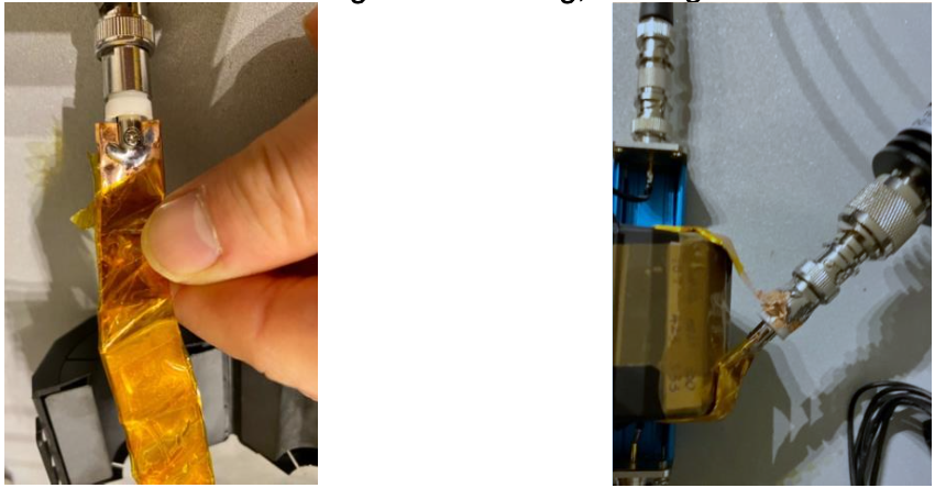
Construction of a single-turn winding is easy, here we used a copper that is about 1.5 cm wide and 12 cm long. Be careful about the sharp edges of the copper when making the winding. The best is to use Kapton tape to wrap around the copper, this provides both protection against the sharp edge and insulation. After that, wind the copper around the core (same core as my previous build, i.e. 28A5131-0A2) and solder a BNC connector to the single turn winding, see Figure 1.
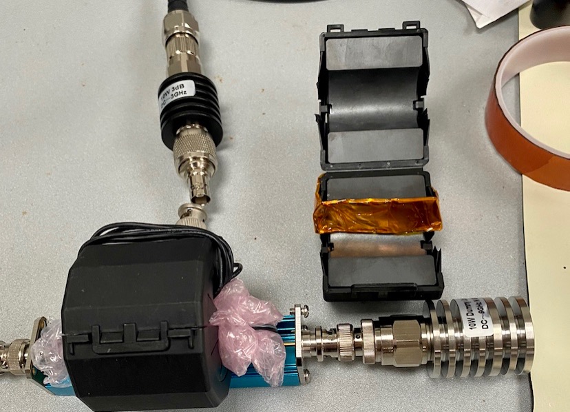
A test jig was also built based on [2], as it can be seen from Figure 2. The two current probes under test were shown in Figure 3.

Test set-up
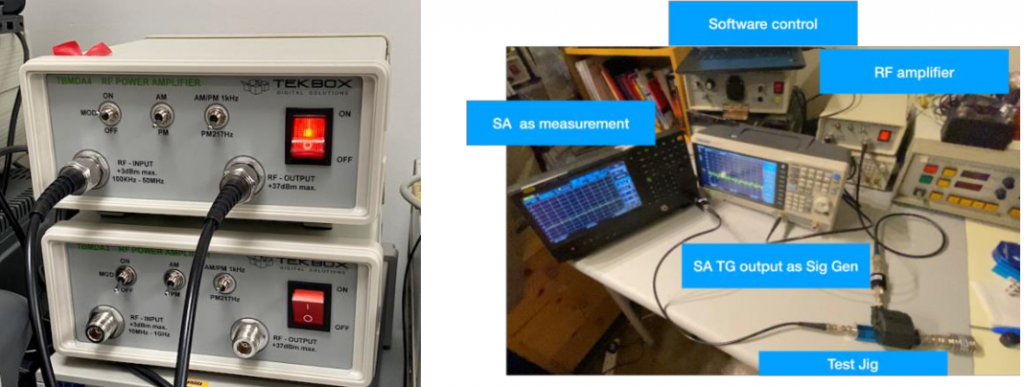
We will need two RF amplifiers to test the frequency range from 100kHz up to 1 GHz. To make things easy, I was using Texbox EMCView software to automatically generate the reference signal (in which frequency, amplitude and dwell time can be set). Two spectrum analysers were used in this case, one is to serve as an RF signal generator (by using its tracking generator output). The other one is used to monitor the injected current on the test jig.
Performance Comparison
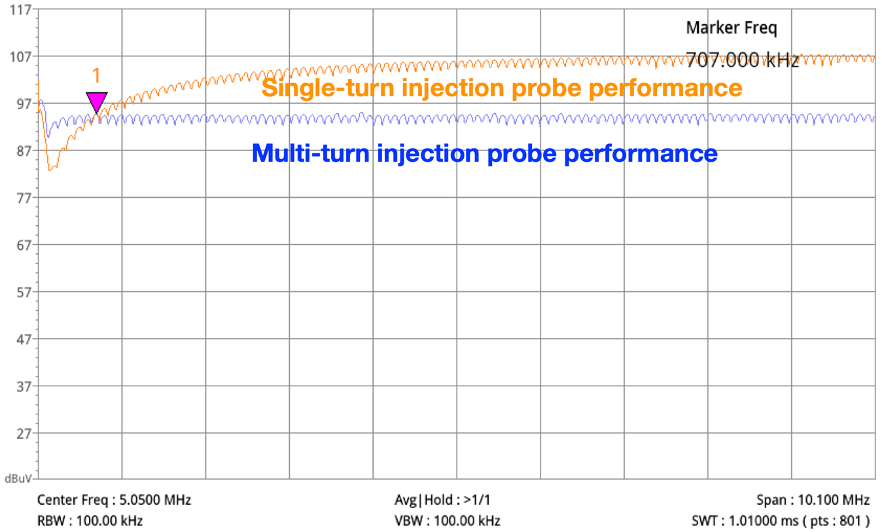
In the frequency range between 100kHz and 10MHz, single-turn winding configuration generates about 12dB more current compared with multi-turn configuration, but at the beginning of the spectrum (from 100kHz to 700kHz), the performance of the single-turn winding is not that good. Note that we measured the injected current in the test jig. The reading needs to be post analysed to get the true injected current level, but for a comparison study, we just look at the dB difference between the two probes.
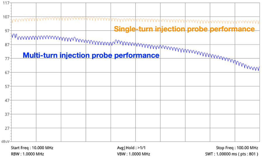
In the frequency range of 10MHz and 100MHz, single-turn injection probe performs much better, its output is flat and achieves higher level of injection current across the full spectrum, while the multi-turn injection probe’s performance starts dropping after 50MHz.
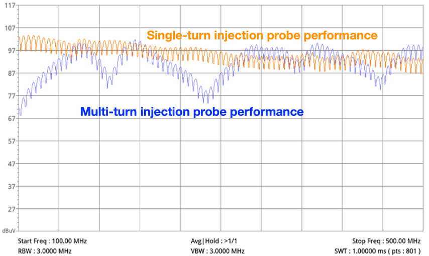
In the frequency range between 100MHz and 500MHz, often a frequency range that automotive companies care about the most, one can see the single-turn winding configuration performs much better (flat and maintains a high level of current level).
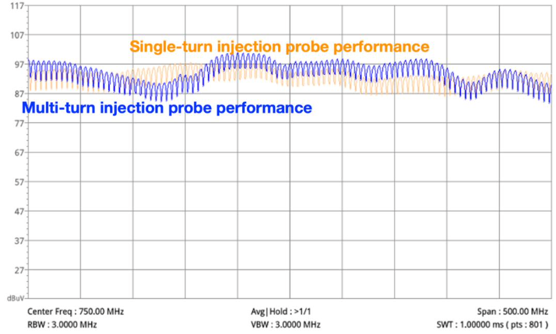
In the frequency range of 500MHz – 1GHz, the performance comparison is shown below:
Injected current level
So what’s the injected current level that is achieved using a single-turn winding configuration? Assuming 100dBμV reading from the test set-up, the 100dBμV was measured on the spectrum analyser (which has a 50Ω input impedance). We had a 30dB attenuator before the reading, so the true voltage reading is 130dBμV. Since it is a quasi-matched system (50Ω on the spectrum analyser and 50Ω at the other end of the line), we can just subtract 34dBΩ(50Ω) from 130dBμV to arrive at 96dBμA, a good level that you need for automotive application.
Explanations of the performance difference
A possible explanation of the performance difference between the two probes are given below.
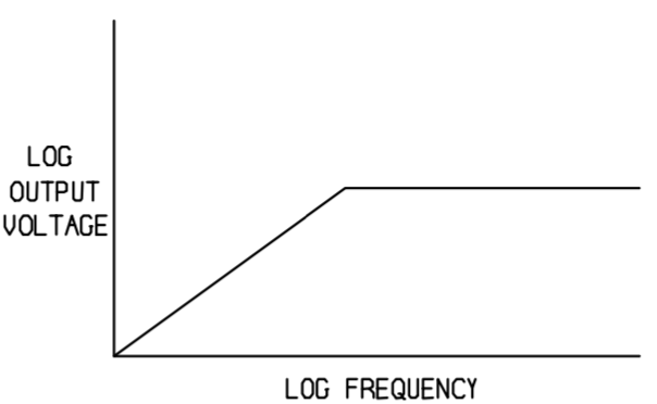
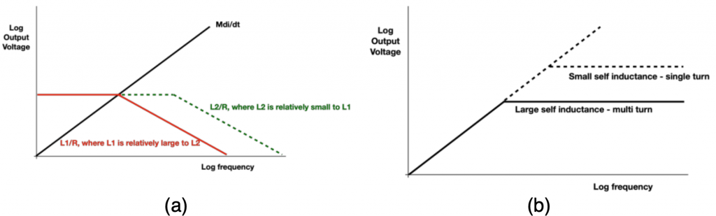
A simplified current probe circuit is shown in Figure 9 [4]. One should note that this model is based on an RF current monitoring probe, rather than an injection probe, but the principle is the same. Because the current monitoring probe is connected with a 50Ω (as the input of a spectrum analyser), the self-inductance forms an L-C circuit with the 50Ω load. This means that the impedance of the current probe against frequency becomes flat after the corner frequency (In Figure 10).

frequency response [4]
In [4], Smith talked about the impact of resistance on the current probe frequency response. Here, we look at the impact of self-inductance on the current probe frequency response. We simulated 2 self-inductance value while keeping the resistance value the same, Figure 11 demonstrates the impact.
Using the probe as a current monitoring probe, we set up a test to compare the performance between the two probes and the result is shown in Figure 12. Frequency span is from 10kHz to 5MHz.
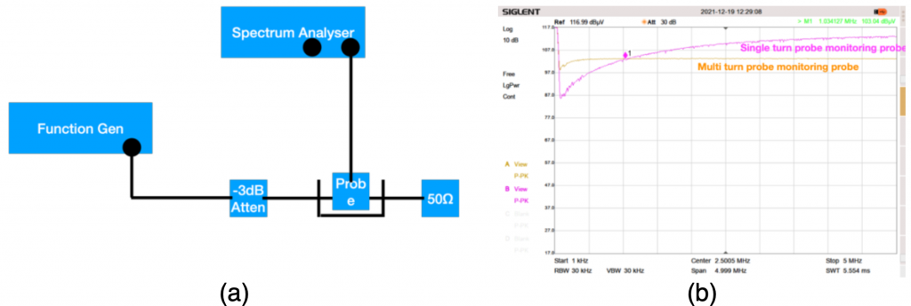
single and multi-turn probe
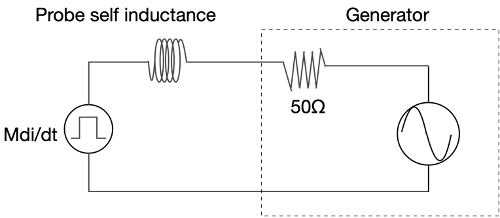
When using the probe as a bulk current injection probe, the simplified current probe circuit is then shown in Figure 13. The mutual coupling depends on the magnetizing current, which at low frequency is limited mainly by the 50Ω resistance. As frequency goes up, the self-inductance starts to limit the magnetising current. Therefore, multi- turn configuration has less mutual coupling compared with single-turn configuration as shown in the test results in Figure 14.
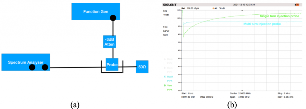
For the single turn configuration of the current injection probe, the corner point is at roughly 700kHz. This explains what is shown in Figure 5.
After 40MHz, the interwinding capacitance starts to take effect, that’s why in Figure 6, the performance of the multi-turn configuration winding starts to drop. At higher frequency, the L-C tank circuit behaviour of the multi-turn configuration means the output is oscillating.
Reference
[1] M. Zhang, “EMC Compliance,” 2021. [Online]. Available: http://emccompliance.co.uk/a-low- cost-bulk-current-injection-test-set-up.
[2] A. Nielsen, “InCompliance Magazine,” 12 2021. [Online]. Available: https://incompliancemag.com/article/application-of-thrifty-test-equipment-for-emc-testing/.
[3] Frederic Lafon;Younes Benlakhouy;Francois De Daran, “ResearchGate,” [Online]. Available:https://www.researchgate.net/publication/280094695_INJECTION_PROBE_MODELING_FOR _BULK_CURRENT_INJECTION_TEST_ON_MUL TI_CONDUCTOR_TRANSMISSION_LINES .
[4] D. Smith, “Current probes, more useful than you think”.