by Dr. Min Zhang, the EMC consultant
One project we got involved has seen a device particularly sensitive to radiated noise in the frequency range of 200 and 400 MHz, also in the frequency range of 800-900 MHz. In other frequency range, the device works without error when exposed to radiated noise or Bulk Current Injected (BCI) noise. This indicates some structure resonance in the system. A structure such as a PCB, trace on the PCB or cable could act like an accidental antenna. This accidental antenna could pick up noise in certain frequency range (depends on the antenna size) and amplifies it. The following article documents a test set-up to identify the issue.
A little bit of theory
The PCB of the device under test (DUT) has a size of roughly 50 mm × 50 mm, forming a 200 mm-long loop (50 mm × 4) , the assumption was that traces and tracks on the PCB must have formed a very efficient loop antenna between 200 -350 MHz frequency range. We know that the electromagnetic wave travels in an FR4 material at a speed of 1.5×10⁸ m/s. Based on equation v=λf, where v is the speed of light in FR4 and f is the frequency. For 200 MHz wave, a full wavelength is then calculated to be 750 mm. A quarter of wavelength (where the radiation is the strongest) is 187.5 mm. So, we are expecting to see the PCB itself resonate at a frequency range of 200 MHz. This would probably amplify the RF noise which is injected from outside.
Test Validation
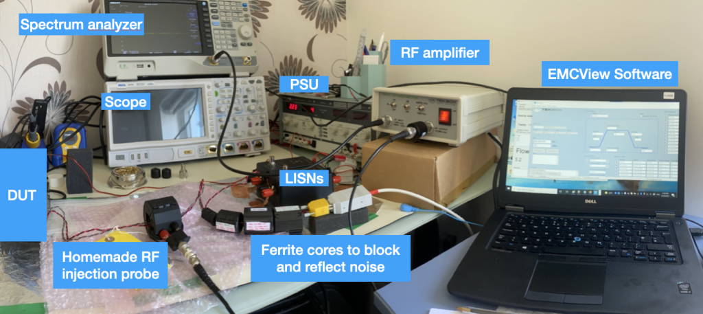
The following test set-up was then performed in our pre-compliance EMC test lab. The workbench test set-up is shown in Figure 1. For more information of how to set up a low-cost BCI test on a workbench, please refer to our article A Low-cost Bulk Current Injection Test Set-up for details.
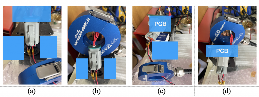
The PCB was first removed from the module, and we simply connected the connector cable to the inner cable inside the module. Note, there’s no physical electrical connection between these two cables, so when injecting BCI type RF noise on the connector cable, the coupling between the two cables is purely by near-field electric/magnetic coupling.
We injected RF noise in the connector cable by BCI method, then measured the RF current in the main connector cable (a) and the RF current in the inner cable(b).
The PCB was later put back, we injected RF noise in the connector cable and measured the RF current in the main cable (c), then the inner cable (d).
The RF current monitoring probe used here is a commercial TBCP4-500 from Tekbox. It has 16 dBΩ characteristics impedance and works in the frequency range of 1 to 500 MHz (Mine works up to 700 MHz). A better type for this test would be TBCP4-750, which covers a frequency range potentially up to 1 GHz. But for us, we focus on the comparative results, so at higher frequency, we could still rely on the current probe results.
A 225 MHz RF noise was injected to the main connector cable first, this is the point where the system failed. We then injected 800 MHz noise, this is the point where the system passed with confidence. What we found was:
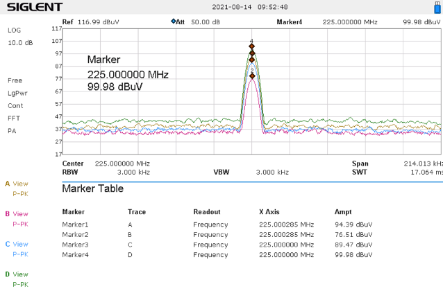
At 225 MHz, RF Current (a) > RF Current (b), but RF Current (c) < RFCurrent (d), see results in Figure 3. Trace A, B C and D in Figure 3 are the measurement results correlating to set-up a, b, c and d as in Figure 2.
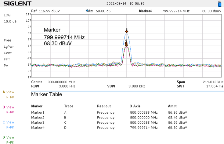
At 800 MHz, RF Current (a) > RF Current (b), same as before. However, we now had RF Current (c) > RF Current (d) as shown in Figure 4. This means, at 225 MHz, the PCB amplifies the signal because the PCB is a strong antenna at this point (1/4 of the wave length). At 800 MHz, the PCB attenuates the signal instead.
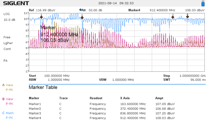
With this finding, a frequency sweep was then performed from 100 MHz to 1GHz. Basically, the RF amplifier injects the same level of RF noise into the main connector cable from a frequency range of 100 MHz and 1 GHz. Here two test set-up points were measured, point (c) and (d) shown in Figure 2. And we subtracted the results, the result is then shown in Figure 5.
The yellow trace showed result in test point (c) and the red trace showed the result in test point (d). The blue trace is the trace of interests since it is the subtraction of test point (c) and (d). Basically, the positive profile shown in the blue trace (as shown from frequency point 1 and 2 and from frequency point 3 and 4) means the PCB amplifies the input signal, whereas at the rest of the frequency range, the PCB attenuates the RF noise (shown as negative profile in Figure 5). We now know why we had immunity issue between 200 MHz and 400 MHz, same with 840-920 MHz.
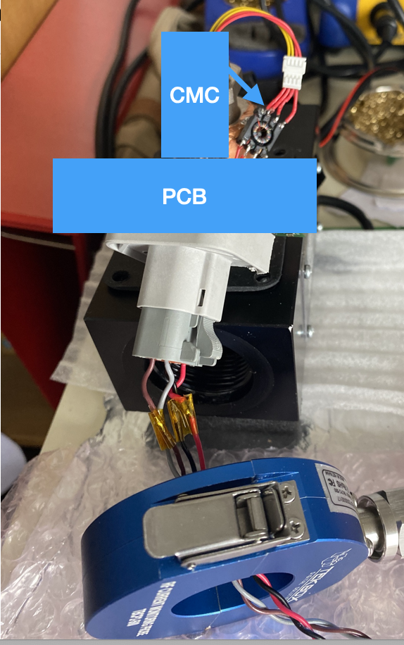
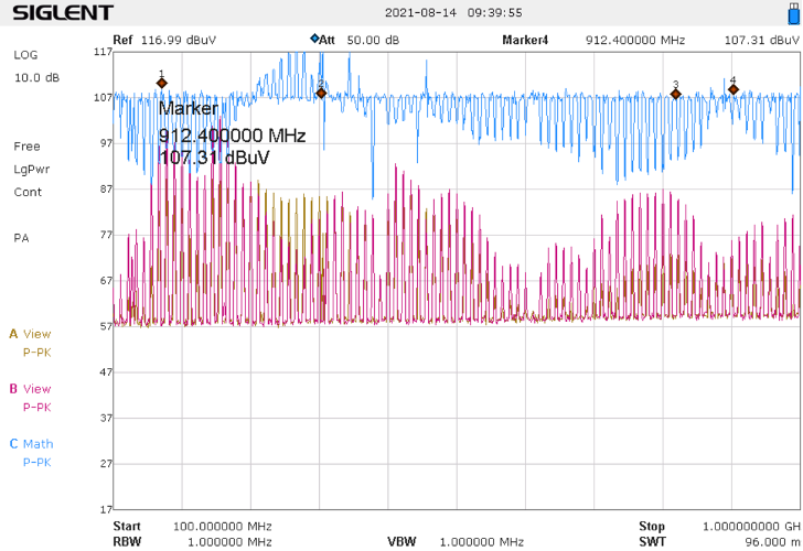
To prove the point even further, the same sweep test was repeated, but now we replaced the inner cable with a cable with a CMC we fitted previously (as shown in Figure 6). We now had the following result. As it can be seen in Figure 7, the amplified region is now limited to about 300 MHZ and 400 MHz. This result aligns with the findings in the trouble-shooting process.
Conclusion:
A test set-up was built to test the noise coupling path in a DUT. It was believed that the PCB of the DUT has a resonant frequency in certain frequency range and as a result, amplifies the noise coming into the PCB. This was later proved by the test, in which an inner cable connected to the PCB actually had much higher RF current level compared with the main connector PCB when noise was injected. The test set-up was unique and innovative in a way that it gives engineers a visual view of how noise is coupled and propagated in a system.
Equipment list used in this test set-up
Power Supply Unit – TTI PL320QMD, old production, manufacturer stopped this unit
Spectrum Analyzer – Siglent SSA 3021X, https://siglent.co.uk/product/siglent-ssa3021x-plus-spectrum-analyser/
LISNs – Tekbox TBOH01 https://www.tekbox.com/product/tboh01-5uh-lisn-cispr-25/
BCI probe – homemade, see http://emccompliance.co.uk/a-low-cost-bulk-current-injection-test-set-up
RF Amplifier – Tekbox TBMDA 3 https://www.tekbox.com/product/tbmda3-modulated-power-amplifier/
RF Current monitoring probe – Tekbox TBCP4-500 https://www.tekbox.com/product/tbcp4-32mm-fixed-aperture-rf-current-monitoring-probes/
Software – EMCView https://www.tekbox.com/product/emcview-pc-software-emc-compliance-testing/
Signal Generator – TTi TGF4242 https://www.aimtti.com/product-category/function-generators/aim-tgf4000