by Dr Min Zhang, the EMC Consultant
This article documents a low-cost Bulk Current Injection (BCI) test set-up For EMC immunity test. BCI tests are widely seen in automotive, aerospace and military EMC immunity tests. It tests the immunity performance of a device under test (DUT).
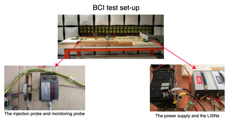
The current injection probe used in proper compliance EMC test is often expensive. This is because to achieve a good level of RF current, one would need to inject a very high level of RF power. In order to prevent the magnetic core of the current injection probe from saturating, the core needs to be thick enough. Standard BCI test also requires an RF current monitoring probe to measure the level of injected RF current. A powerful RF amplifier is also required to drive the probe, this increases the cost of the test. A snapshot of BCI test is shown in Figure 1.
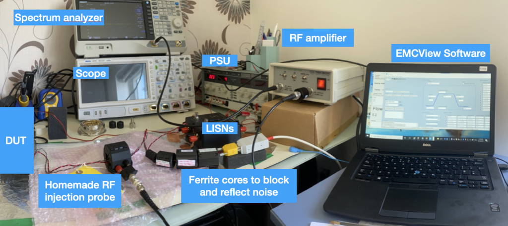
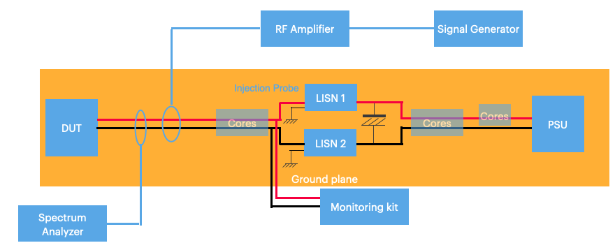
One can easily create a similar test set-up with only a fraction of the cost that a compliance EMC test would normally involve. Such a test set-up can be see in Figure 2. We will go through the details of each unit in this set-up. A simplified system diagram of the test set-up is shown in Figure 3.
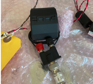
A homemade injection probe
A homemade RF current injection probe can be easily made by wiring a few turns of wires of a snap-on ferrite core[1]. Two things need to take considerations here. One is the core size. As mentioned before, we need a thick core with a good frequency range. A Laird (now Dupont) 28A5131-0A2 is a good candidate. It is a bulky ferrite core and the 28 material has a good frequency response (10-1000 MHz). You would need an RF BNC T-piece adaptor to connect the two ends of the wires, so the signal comes in with BNC connector and splits into signal and ground. A homemade current injection probe is shown in Figure 4.
Applying ferrite cores between the BCI and the LISNs & monitoring kit
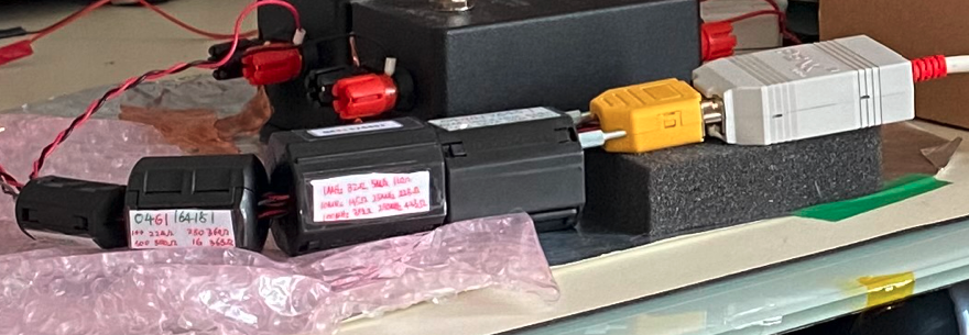
In [2], Ken Wyatt recommended put a few ferrite cores between the DUT and the LISNs. The ferrite cores serve two purposes. One is to reflect RF energy so that more RF current is injected into the DUT. Second purpose is to attenuate the noise that goes into the monitoring circuit. Often the monitoring circuit is through LIN, CAN, Flexray, etc. If too much RF noise goes into the monitor module, you would not tell whether it is due to the DUT failure or simply the monitor kit had problem. So it is very important to apply a few ferrite cores between the BCI injection probe and the LISNs. But Ken didn’t give specific types of the ferrite cores one should use. Here, we used 4 different core materials from fair-rite. These materials are 75 material(200 kHz – 30 MHz), 31 material (1-300 MHz), 43 material (25 – 300 MHz) and 61 material (200 – 1000 MHz). The idea is simple, we want to achieve a wide bandwidth of noise reduction to the monitoring circuit. A ferrite core selection between the BCI injection cable and the LISNs & monitor kit can be seen in Figure 5.
LISNs and power supply unit
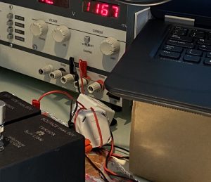
We used two DC LISNs from Tekbox, TBOH01 and Tekbox has an excellent document detailing how to set up LISNs for conducted emission measurement [3]. We basically set the LISNs up following [3], note there’s a 1000 μF electrolytic capacitor linking the two LISNs, [3] explains why. Between the LISNs and the power supply unit, we also put some ferrite cores as both common-mode choke and differential inductor. The reason for this that the power supply unit we use also produces RF noise. In order to make sure this noise does not interfere with the system under test, we used the CMC and inductor together with the capacitor to form a good low-pass filter. For both the CMC and the inductors, we used two-turn to three-turn winding configuration to increase the impedance. Figure 6 shows the details.
RF Amplifier
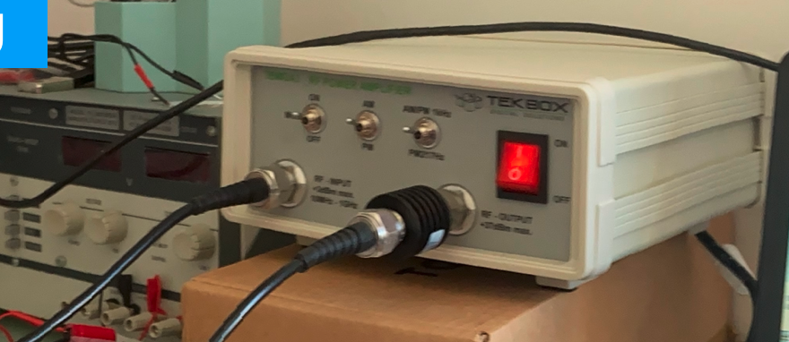
We used Tekbox TBMDA3 as the RF amplifier, this amplifier has a forward power of up to 37 dBm and the frequency range is between 10 MHz and 1 GHz, perfectly built for this task. For a full review of this product, I would point you to Ken Wyatts’s blog [4]. It should be noted here that in order to prevent impedance mismatching of this amplifier, it is highly recommended to connect a 3 dB attenuator to the output of the unit. Here we connected a 10 Watt 3dB attenuator, considering the high power output of this product.
Spectrum Analyzer and Signal Generator
The input signal can be generated either from a spectrum analyser with a tracking generator (TG) function, or a signal generator. Obviously, if you only have one spectrum analyzer, and you want to use a current monitoring probe to measure the RF current on the line, then using a signal generator is your only option. I have two spectrum analyzers and one signal generator, so I have the freedom of using either. But my signal generator (TTI TGF 4242) is limited to 240 MHz, so for high frequency noise injection, I need to use my Siglent spectrum analyser (SSA 3021X) which has an output up to 2.1 GHz.
Current monitoring probe
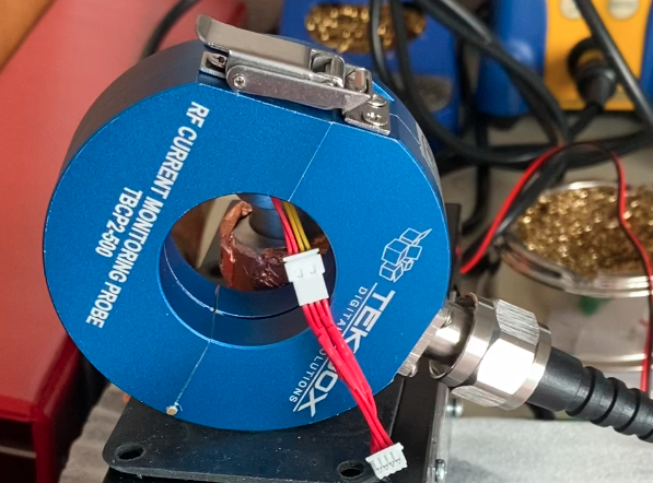
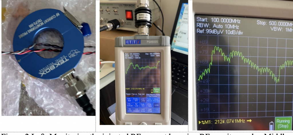
This is an option. if you want to monitor the injected RF current level, then consider using a characterised RF current monitoring probe. This can be done either by a homemade probe [1] or by a commercial current monitoring probe. We used Tekbox TBCP4-500 current monitoring probe. Obviously, this probe works only up to 500-600 MHz. Preferably, one would need their TBCP4-750 probe to cover a much wider frequency range. The best thing of using characterised current probe is that you can work out the RF current value (in dBμA) based on equation dBμA=dBμV-dBΩ.
Software
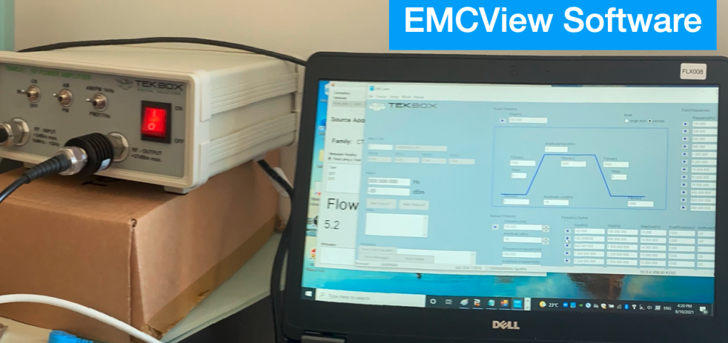
The signal generator of mine has the frequency sweep function and it is very useful if we want to sweep a frequency range of BCI noise. But due to its upper frequency limit, I sometimes need to use my spectrum analyzer to generate the reference signal. In such cases, I found using Tekbox EMCView software is extremely useful. In this case, I use the generator function built within the software and it gives the flexibility of using frequency sweep, changing injected current level. A snapshot of the software used as a generator mode is shown in Figure 9.
Test Result
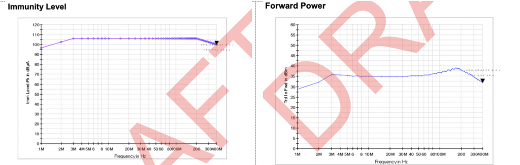
We tested the pre-compliance BCI test set-up against an accredited EMC lab test report and result is amazingly similar.
The power amplifier has a maximum forward power of 38 dBm, but we used a 3dB attenuator to prevent impedance mismatch of the RF amplifier, this should give us 35dBm (38-3dBm) maximum output power. With a current monitoring probe attached to the cables (see Figure 10), the injected current was measured and calculated to be roughly at 100 dBμA. Calculation is based on 85dBμV reading (from spectrum analyzer) +30dB(due to attenuator attached to the handheld spectrum analyzer RF input) -15dBΩ(current probe impedance). This current level is very close to the BCI test set-up in the accredited test house (see Figure 11). The forward power in the EMC test house is 35dBm and the RF current was measured to be 105 dBμA).
Summary
In this article, a low-cost BCI test set-up is introduced. The whole test set-up uses cost-effective equipment and instrumentation, resulting in an economical way of reproducing the BCI test failure that only accredited TEST house could test. Test results showed similar results in current level and forward power level. We have been using this set-up to help our clients solve many EMC problems.
Reference
[1] K Wyatt, the HF current probe : Theory and Application, http://www.interferencetechnology.com/wp-content/uploads/2012/04/Wyatt_NA_DDG12.pdf
[2] P.G. André & K Wyatt, EMI Troubleshooting Cookbook for Product Designers
[3] M Mayerhofer, Conducted emission measurement using the Tekbox 5μH LISN TBOH01, https://www.tekbox.com/product/AN_Conducted_Noise_Measurement_TekboxLISN_TBOH01_EMCview.pdf
[4] K Wyatt, Using high-powered RF immunity testing, https://www.edn.com/using-higher-powered-rf-immunity-testing/