When it comes to high frequency noise suppression, near-field coupling could mean the applied filters fail to work. In this case, even though multi-stage filters are applied, the results are simply not improving. It is then time to look and think out of the box – literally and figuratively.
By Dr. Min Zhang, the EMC Consultant
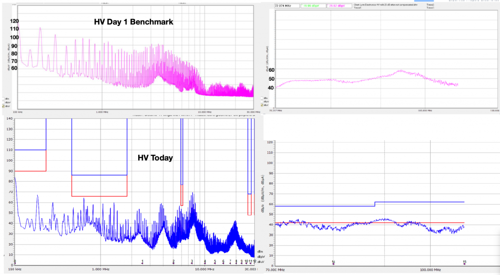
Recently I had the pleasure of working on an automotive DC-DC converter. The conducted emission on the HV side was quite bad, the noise profile means that the conducted emission failed the limits (defined by CISPR 25) almost at every frequency range.
Since the conducted emission failed at such a wide frequency range, we designed a multi-stage filter which consists of both differential mode (DM) and common mode (CM) filtering. We expected the DM part of the filter would work effectively at lower frequency range (150kHz-5MHz) while the CM part would suppress the noise at higher frequency.
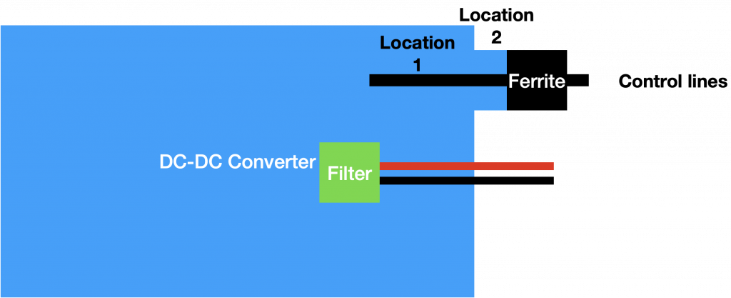
This worked well as shown in the picture below. However, between 70 and 110 MHz range, we are still above the limit line. Initially, I told the client that it is very easy to suppress the noise at this frequency range as we can apply common mode choke, together with low impedance caps to chassis. But this approach didn’t work at all. What is most interesting, is when we placed a 3-turn 31 ferrite material inside the DC-DC box, the situation simply didn’t budge.
The first sign of near-field coupling
One thing which we found very interesting was that the same ferrite core, with 2/3 turn configuration, when placed inside the box and outside the box, had completely different conducted emission results (see below). When placed outside the DC-DC container, just after the connector, we can see 10-20dB reduction in the frequency range of interests. But when placed inside the box, there was no improvement.
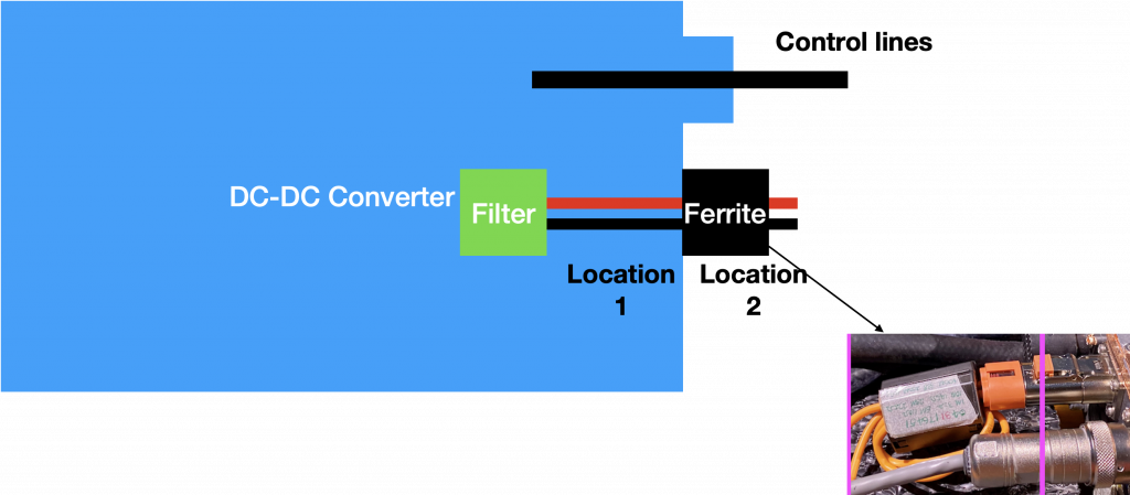
We knew this is because of the near-field coupling between the HV lines and the control lines nearby. But at the time, we couldn’t figure out why this coupling is so strong that a ferrite at location 1 (inside the box) simply didn’t do anything.
The second sign of near-field coupling
We confirmed the near-field coupling by the following test. When we placed the same ferrite on the control lines (either inside the box or outside the box) and measured the conducted emission on HV lines, we found the noise in the frequency range of interests reduced. This is a penny drop moment.
So, we spent lots of time trying to suppress the high frequency noise on the HV lines, only to find that the filters were applied at the wrong locations. This highlighted the issues of near-field coupling and how strong this coupling could be. If the signs of near-field coupling were overlooked, we could have spent ages trying to chase a wild goose.