By Min Zhang, the EMC Consultant
- Background
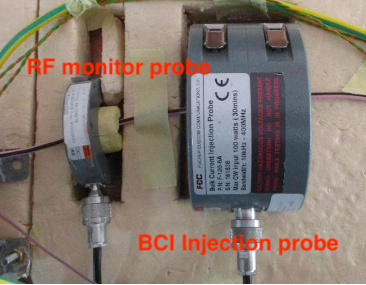
For EMC testing in the automotive, military and aerospace sectors, a Bulk Current Injection (BCI) test is widely used as an immunity test method. This test requires a high-power amplifier (often at least 80 Watt unsaturated output power), together with a BCI injection probe, to achieve a reasonably high interference level on the device under test (DUT). The BCI injection probe and monitor probe are shown in Figure 1.
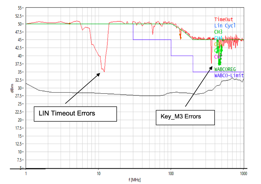
In this example, an automotive remote controller unit has experienced immunity issues during the BCI test in an accredited testing laboratory. The Local Interconnect Network (LIN) of the module lost communication in the frequency range between 5 and 15 MHz. The BCI test results are shown in Figure 2.
As always, to fix an EMI issue, the same failure mode needs to be reproduced in a pre-compliance EMC test set-up. For pre-compliance EMC tests, unless the specific BCI test equipment is available, to reproduce the same failure mode often requires a different set-up. In this article, a capacitively coupled pin injection method as an alternative is presented.
2. Commonly used pre-compliance immunity test techniques
The following test set-ups are the most commonly used in pre-compliance EMC immunity tests:
- A workbench BCI test using an RF monitor current probe as an injection probe.
- A Coupling and Decoupling Network (CDN) method.
- A Transverse Electro-Magnetic Cell (TEM Cell) method.
- A Capacitively Coupled Pin Injection method.
- Other methods such as chattering relay.
It is often down to an EMC engineer’s personal preference to select a test method that is best suited for pre-compliance EMC test. For instance, a Fischer current monitor probe F-33-1 is often seen being used as an injection probe for pre-compliance BCI test [1]. The test set-up was documented in detail [2]and it was mentioned that in order to achieve a higher level of RF interference, one would need to put some ferrite chokes on the other side of the probe to reflect more energy to the DUT.
While this method might work to some extent, it is generally not a good practice to use an RF monitor probe to inject noise, unless you know the specified maximum RF power that you can feed into the probe. Besides, most of the RF monitor probes are designed to receive rather than emit RF signals. BCI injection probes typically have a very large cross section toroid to increase the saturation levels (see Figure 1).
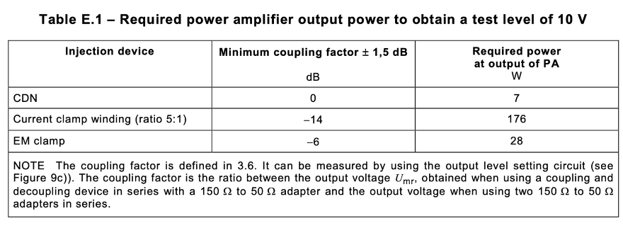
Today, using a CDN is the recommended choice for immunity test [3]. As one can see from Table 1 (Table E.1 from [4]), compared with a BCI test, a CDN requires a much smaller power level to achieve a higher coupling factor. Using a TEM cell for immunity test is also gaining popularity [5], studies have shown that there is a strong correlation between the TEM cell and BCI test results [6].
In the following example, a suitable pre-compliance immunity test needs to be selected. Before the capacitively coupled pin injection technique was introduced, a work bench BCI injection and a TEM Cell immunity test were applied. Test set-ups for both are shown in Figure 3. In both cases, the power amplifier used is Tekbox TBMDA4 [7] which can produce up to 37 dBm output power (5Watt power over a 50 Ω load) from 100 kHz to 50 MHz. Neither of these methods could re-produce the failure modes as seen in the actual BCI test.
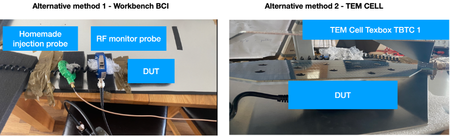
The reasons for failing to reproduce the failure mode using the workbench BCI test set-up could be that the core of the home-made injection probe was saturated during the test, or simply, the power level was not large enough. Adding multiple ferrite cores on the other side of the current injection probe proved to have little impact during the test.
The open TEM Cell (Tekbox TBTC1) used during the test could potentially achieve a field strength of 300V/m, a strong field exposure for the DUT. Immunity testing of a device in a TEM cell requires testing of at least three orthogonal DUT positions. The direction of the electrical field is orthogonal to the septum. A typical mechanism of immunity issues are PCB traces acting as antennae and coupling RF into semiconductor junctions, where the RF is rectified, resulting in bias voltages or offsets which then cause malfunction of circuitry. As PCBs typically have traces routed in two main directions, orthogonally with respect to each other, it is the best practice to test the DUT with the PCB plane orthogonal to the septum and then rotate it 90 degree, but still orthogonal with respect to the septum [8]. Two positions of the DUT were tested in this case, the failure mode was not reproduced.
3. Introducing the capacitively coupled pin injection method
3.1 Test set-up
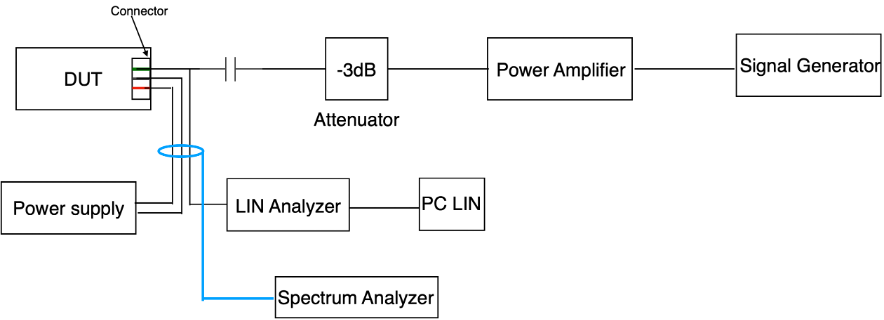
A diagram of the test set-up is shown in Figure 4 and an image of the test set-up is shown in Figure 5. An RF current monitor probe was clamped to the cable to monitor the injected RF current level during the immunity test. Note that the current level depends on the output of the RF amplifier, the impedance of the capacitance value of the injection probe and the circuit impedance of the DUT.

3.2 Making a “flying” probe
The injection probe used in the test is also referred to as a “flying” probe for the reason that the capacitive probe often has a small ground plane to increase the coupling between the probe and the DUT’s power/ground plane, the small ground plane looks like a “wing”, hence the name “flying” probe (or “wing” probe).
It is easy to make a home-made “flying” probe as shown in Figure 6. Cut a semi-rigid coaxial cable into half, drill a hole with the same diameter as the coaxial cable in a small piece of copper and solder the piece of copper to the shield of the coaxial cable. Use a small size PCB with good ground plane is also a good idea. The tip of the coaxial cable signal line is then soldered to a 250V capacitor. The value of the capacitor depends on the level of interference current one would like to inject.

3.3 Selecting the right size of a coupling capacitor
The injected RF current level depends on the source impedance of the amplifier, the capacitance value and the load impedance. Often the load impedance is unknown and it is frequency dependent. The general rule is that at the frequency range of interest, the impedance of the capacitor should be more or less the same as 50 Ω (to match with the RF amplifier output impedance). For instance, if the DUT has an immunity issue at 68 MHz, then a 47 pF would be a good choice, because the impedance of a 47 pF capacitor at 68 MHz is about 50 Ω. If the DUT has immunity issues below 30 MHz, then a 100 pF capacitor would be a better choice. Most of the RF amplifier will have a high voltage device rating against impedance mismatch. To prevent impedance mismatch of the power amplifier, often an attenuator (such as a 3 dB one) is also recommended to be connected between the output of the power amplifier and the “flying” probe.
Because the failure mode occurred at sub 20 MHz range in this particular case, a 100 pF, 250V Y-Class capacitor was selected. It is also important to note that the equivalent series inductance (ESL) of a capacitor only has little impact at this frequency range. However, when the frequency starts increasing, the long lead of a capacitor will start dominating the impedance as parasitic inductance increases with frequency. Therefore, if the injected noise level is in the hundreds of MHz range, the impedance vs frequency curve of the selected capacitor needs to be checked to make sure the impedance of the capacitor is not too high. Long leads of the capacitor will certainly need to be shortened in the MHz frequency range.
3.4 Test results
The test was simple to perform. One just needs to make sure that the RF amplifier input level limit is not exceeded, by supplying the right amount of input signal. The signal generator was configured to do a fixed amplitude variable frequency sweep between 5 and 15 MHz.
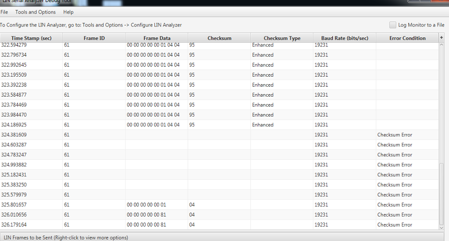
It was noted that the LED lights of the DUT started flashing during the sweep, the PC monitor also recorded multiple LIN communication errors shown in Figure 7. This was the same behaviour the DUT experienced in the BCI test. The current which was monitored through the RF monitor probe gives another useful tool to identify the potential issue on the circuit.
With the failure mode being able to be seen in the pre-compliance test set-up, fixing the issue and validating the results become possible.
4. Conclusion
A remote controller module used for automotive application has experienced communication failure during the BCI test. In order to fix the problem, a pre-compliance immunity test was set up. It was found that a Capacitively Coupled Pin Injection method was able to reproduce the same failure mode, while other alternatives failed to do so.
The test set-up and the construction of the pin injection probe were demonstrated, details of the capacitor selection were explained.
For pre-compliance immunity test, the proposed method should serve as an easy and effective alternative to the BCI test.
Reference
| [1] | K. Wyatt, “Using higher-powered RF immunity testing,” EDN, 25 May 2021. [Online]. Available: https://www.edn.com/using-higher-powered-rf-immunity-testing/. |
| [2] | P. a. K. Wyatt, EMI Troubleshooting Cookbook for Product Designers, Edison: SciTech Publishing, 2014. |
| [3] | K. Armstrong, A Practical Guide for EN 61000-4-6: Testing and measurement techniques – Immunity to conducted disturbances induced by radio-frequency fields, REO UK LTD. |
| [4] | I. Standard, IEC 61000-4-6 Edition 4.0 2013-10, IEC, 2013. |
| [5] | A. Eadie, “TEM Cell and GTEM Guide For Radiated Emissions & Radiated Immunity Pre-Compliance Testing,” [Online]. Available: https://emcfastpass.com/tem-cell-guide/. |
| [6] | D. Trout, “Investigation of the Bulk Current Injection Technique by Comparison to Induced Current from Radiated Electromagnetic Fields,” NASA, George C. Marshall Space Flight Center. |
| [7] | “www.tekbox.com,” [Online]. |
| [8] | “FAQ Tekbox open TEM-Cells,” [Online]. Available: https://www.tekbox.com/product/QA_OpenTEMCells.pdf. |