by Dr. Min Zhang, the EMC Consultant
This article compares the TEM Cell results (near-field) against antenna measurement (far field).
A detailed video demonstration can be found in https://youtu.be/vqxdSD-i0lY.
Some details with regards to the test set-up.
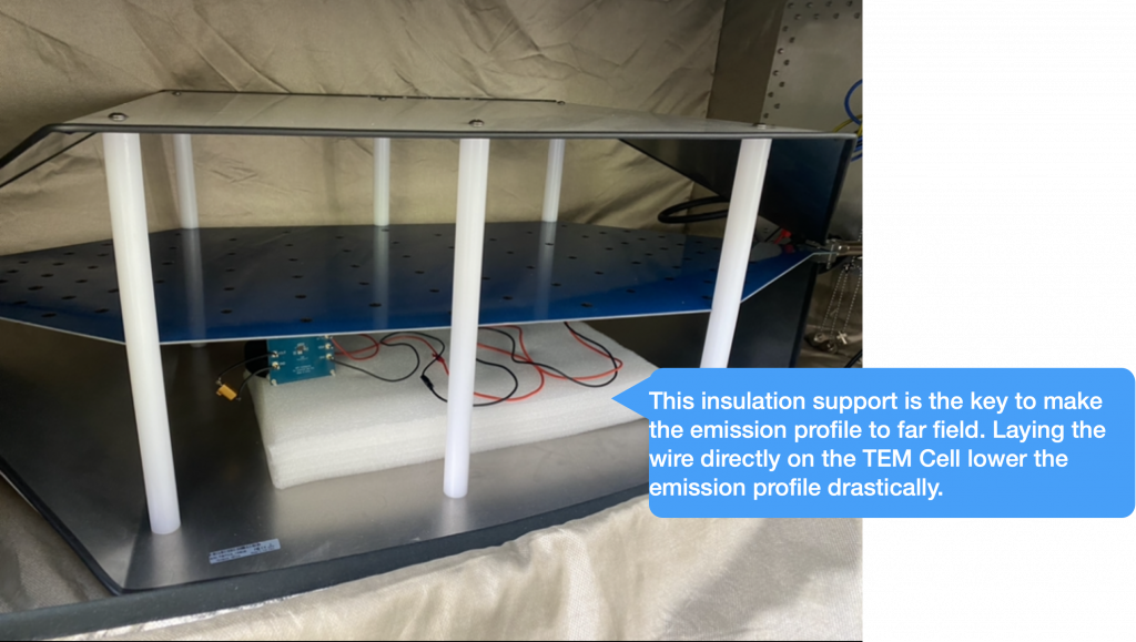
- The TEM Cell unit we used is Tekbox TBTC-3, a large TEM cell compared with other TEM cells. This TEM cell has a spectrum height of 15cm, which is suitable for many units, especially PCBs.
- The TEM Cell is located inside an EMC shielding tent, this is desirable as for radiated emissions, an open TEM Cell will pick up ambient noise.
- The effective area inside the TEM cell is defined by the standard, the DUT needs to be placed inside the defined area within the TEM Cell.
- The insulation support is very important, here, we used 5cm tall insulation support and we made sure that the wires are placed on the insulation support.
- The wire length is chosen to be more or less the same as what the standard defines, i.e. in this case, between 1.5 and 2m. However, due to the constraint of the space, the wires are meandered, this would affect the radiation profile.
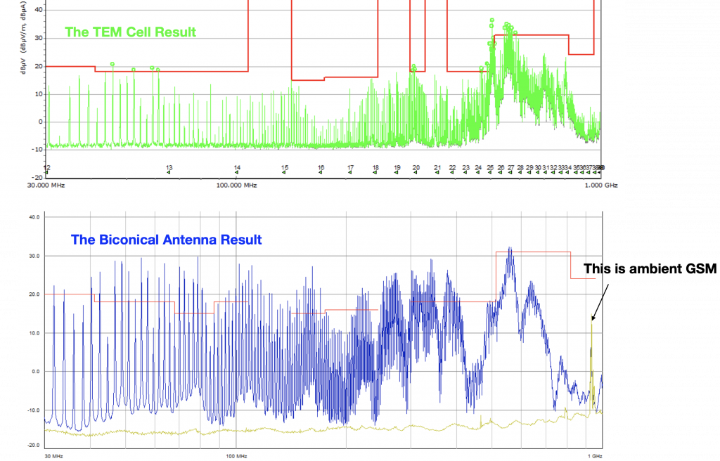
The following diagrams compared the TEM Cell results with that of the far field measurement (according to CISPR 25, 1 meter antenna location to the DUT).
A second DUT is tested.

The comparison results are shown below.

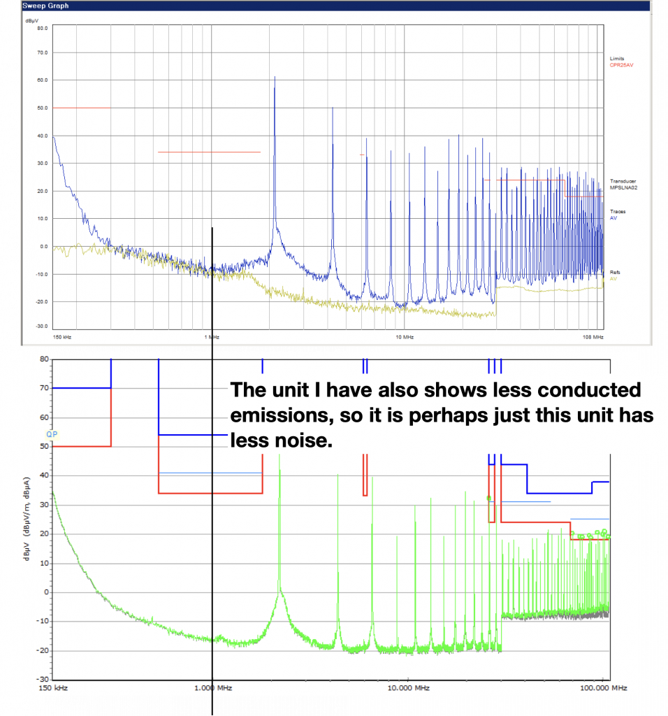
This might be explained by the fact that the DUT has also less conducted noise compared with the benchmark unit. See below:

If the conducted emission level in the DUT is 8 dB less, it explains why the radiated emission level of the DUT is also lower than the benchmark unit.
Overall, the TEM Cell result shows a very similar noise profile compared with the far field measurement. We are confident to use this method as a pre-compliance test set-up.