For RF and EMC engineers, terms such as dB, attenuation, insertion loss, impedance characteristics are their mother tongue (although some speak better than others). But if you are an electronics engineer, a power electronics engineer, or a system engineer, you might be confused by these EMC jargons. In this article, we use simple math equations to demystify the term ‘attenuation’. You will see a few practical day-to-day examples which might confuse you in the past, but hopefully after reading this article, they will make perfect sense.
Case 1 : The 50 Ohm Puzzle
If you have a spectrum analyser with TG (Tracking Generator) function, or even better, a network/impedance analyser, you can measure the attenuation of a simple 50 Ω feedthrough terminator. Figure 1 shows the test set-up, frequency sweep range is between 10 kHz and 1 GHz. Cable was normalised before the 50 Ω feedthrough terminator is connected. One can notice two things from this simple test set up, first is the frequency response (which correlates to the characteristics impedance of the terminator) is not flat (with oscillation rather than a straight flat line). Second is that the 50 Ω feedthrough terminator has about 3.5 dB attenuation.
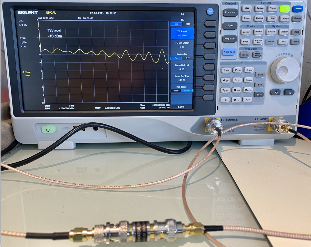
If a 3 dB attenuator is tested, the result is very similar, but with much flat response than the curve shown in Figure 1. So why does 50 Ω feedthrough terminators give 3.5 dB attenuation?
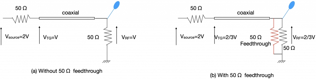
Notice, both the TG output and the RF input has 50 Ω impedance. If the coaxial cable is 50 Ω impedance, and assuming it is a lossless transmission line, the ‘resistive’ part of the coaxial cable is ignored, we have a potential divider circuit shown in Figure 2 (a). The attenuation is defined by VRF/(Vsource/2), not VRF/Vsource! (You will see why) So in this case, attenuation is V/(2V/2)=1, which correlates to 0 dB attenuation. In Figure 2(b), the 50 Ω feedthrough effectively is paralleled with the 50 Ω receiving impedance, this changes the ratio of the potential divider. As a result, we have VRF=2V×[25/(25+50)]=2/3V. So the attenuation is (2/3V)/(2V/2)=2/3, which correlates to 3.5 dB attenuation.
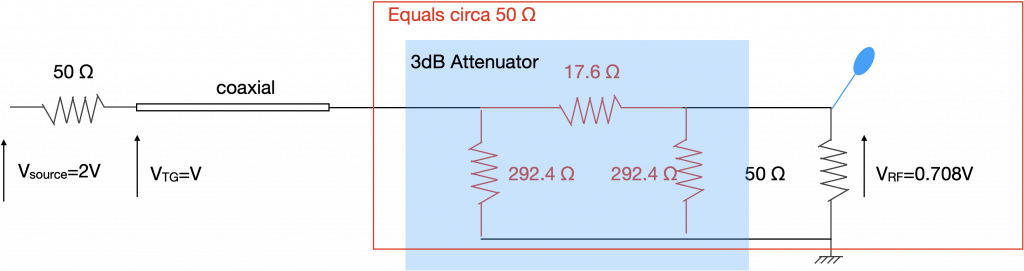
In comparison, a 3 dB attenuator often has a π (sometimes T) impedance network shown in Figure 3. We can work out the attenuation by simple calculation. 292.4 Ω in parallel with 50 Ω gives 42.7 Ω. VRF is then calculated as V×42.7/60=0.708V. The attenuation is 0.854V/(2V/2)=0.708, which correlates to -3dB.
This also explains why some of the function generator manufacturers specify the output of their units differently. If the output is high impedance, the peak-to-peak voltage Vpp is often shown two times of the value if a 50 Ω impedance is used. In fact, most of the function generators have the output function that users can select either high-impedance or 50 Ω. And you will notice, by changing the output loads, the Vpp will either be doubled (from 50 Ω to high-Z) or halved (from high-Z to 50 Ω).
Case 2: Self-made Voltage Probe Ratio
In article A Homemade Balanced Voltage Probe, we first made two matched resistive passive probes which have 750 Ω tip resistor and 50 Ω resistance between the tip and the shield. When measuring the frequency response of these probes, we noticed that the probes give about 23 dB attenuation, but the probe is used as a 31 × ratio probe. 31 × ratio suggests a 30 dB attenuation, so why did we see a 23 dB attenuation when measuring with the spectrum analyser?
This is again relating to the 50 Ω resistor of the TG source output. When defining the probe ratio, we don’t assume there’s a 50 Ω source resistor, rather, we treat the signal we want to measure as an ideal voltage source. So in this case, the ratio of the probe is simply calculated as 25/(25+750)= 0.032, or rather 1/0.032=31. But when we measure a 50 Ω source, we need to take the 50 Ω into account. Therefore, VRF=2V×25/(25+50+750)=0.060606V, attenuation is again VRF/(2V/V)=0.060606, correlating to attenuation of 24.35 dB.
Conclusion
Attenuation in the dB form is specified by RF engineers who use 50 Ω receiver and also 50 Ω source impedance. When use on the real circuit, where 50 Ω source impedance is not always there, the attenuation value could be different. When talking about probe ratio, it is better to stay with the 10× or 1× term to avoid confusion.