A spectrum analysers is perhaps the most important equipment for an RF/EMC engineer. There are many manufacturers who are specialised in making spectrum analysers that can measure signals across a frequency range from DC to tens of GHz. Among these manufacturers, you have the top end manufacturers such as Rohde & Schwarz, Keysight. In the low-cost entry level market, Rigol and Siglent are popular choices because of their low cost.
For self-employed engineers or small companies, spending tens of thousand dollars on an equipment might not be practical. Therefore, entry-level spectrum analysers that are worth under 2,000 USD are the go-to equipment.
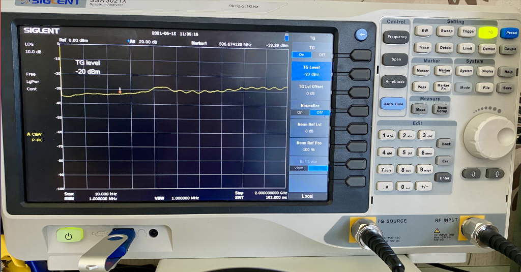
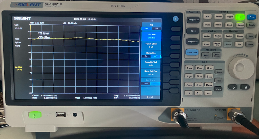
I have a Siglent SSA 3021X with a tracking generator (TG) option which has been helping me troubleshoot hundreds of products/systems for my clients. Recently, however, I noticed that there has been a consistent measurement inaccuracy when I used the equipment. To demonstrate this point, one can simply connect a cable between the TG output and the RF input and do a full TG sweep. As one can see from Figure 1, the TG outputs -20 dBm, but the RF input reads about -35 dBm, 15 dB difference. This measurement is consistent across the whole frequency range.
Problems like this often indicates that the RF input of the spectrum analyzer was damaged. One of the issues with the entry-level spectrum analysers are that the RF input stage is very susceptible to low-frequency (sub 10kHz) harmonic contents. Although each spectrum analyzer has a specific maximum RF input (the Siglent SSA has a max 30 dBm input limit, for instance), they are not designed to be exposed to low-frequency harmonics environment for a long time (a few minutes), even though the power level is perhaps 0 to a few dBm.
The problem is that we have seen an increased number of motor drive, power converter applications in recent years. And these products all have big harmonics contents in the frequency range of a few kHz to MHz. When using a spectrum analyzer to do a conducted emission test, because the frequency range starts from 150 kHz, you might not even realise that the RF input of the spectrum analyser has been under extremely high amplitude stress. So there’s a very big chance of damaging the RF input of the spectrum analyzer. I was measuring a motor drive during its active discharge state and the RF input was damaged as a result.
The cost of repairing the front end is often not cheap and it could take months. The timing issue is particularly true considering the global shipping and supplying chain disruption caused by Covid. The shortage of chips also play a part. As a result, you might find it a lot easier to buy a new part if your spectrum analyzer is damaged.
If you are a hands-on person, then replacing the RF input by yourself might be the best solution. In this video https://www.youtube.com/watch?v=2iAmuLCg2wc, I demonstrated how to fix the RF input of a spectrum analyzer. The key components are
- RF switch, for Siglent, the part number is MASWSS0181TR-3000, which you can buy from Digikey https://www.digikey.co.uk/product-detail/en/macom-technology-solutions/MASWSS0181TR-3000/1465-1389-1-ND/4430086 . For Rigol, the part number is HMC221B
- ESD diodes, BAR63-02V(Infineon) and BZX84J-C30(NXP)
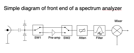
In the video, I didn’t explain what it means for these components in a spectrum analyzer, so I now take the opportunity to demonstrate the front end circuit of a spectrum analyzer, see Figure 2. As one can see, even with the ESD diodes and decoupling cap in front, the RF switch could be damaged if the transient level is high or lasts for a long time. It is therefore highly recommended here that to replace the front end ESD diodes together with the RF switch.
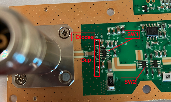
The chips and diodes that need to be replaced are shown in Figure 3.
After replacing the RF Switch 1, the spectrum analyzer went back to normal again. However, only after a week, there’s a different issue observed in Figure 4. This, although is different compared with before, still does suggest something wrong with the front end of a spectrum analyzer. After tracking component to component, it was found that it was the second switch SW2 that caused the issue.
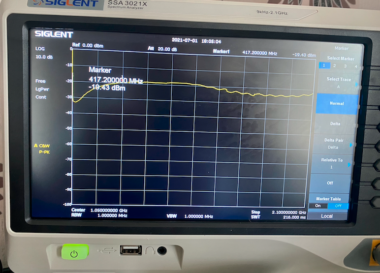
It was quite clear that the transient events must have damaged the RF switch 1 in the first incident and also hurt the switch 2 quite badly. It only took a week before the second switch went down. Now that both switches are replaced, the spectrum analyzer reads correctly again (Figure 5).
Now, it is a lesson learnt that one should always consider protecting the RF input of a spectrum analyser when measuring unknown signals. The best way of doing so is prior to the measurement, use a transient limiter and/or a high pass filter (9kHz). Since the damage, I now use a Tekbox TBFL1 transient limiter https://emcsupplies.com/collections/rf-accessories/products/tbfl1-transient-limiter to protect the RF input of the spectrum analyzer.
The Youtube Video link is