by Min Zhang, the EMC Consultant
When designing a power converter, often the design of DC link is less considered compared with filter design. For many engineers, design for EMC is all about having a place holder for both input and output filters. Multi-stage, double-pole, 40dB attenuation, all these terms just sound very professional when talking about design for EMC, isn’t it?
Having a low impedance DC link is crucial for a power converter design, as it serves the front line of the system. Recently, a few cases in both the automotive and industrial applications just demonstrated this point nicely. You might find the following case studies quite fascinating.
Case 1: Transient failures in 5 kHz burst mode but not 100 kHz!
The device under test (DUT) is a high voltage (HV) electric motor used in an automotive application. One of the HV immunity test is ‘Burst C’ test. Basically, the DUT will experience a string of very fast transients on the DC bus line (also on the V+ to GND, and V- to GND). The transient waveform is the same as that defined in IEC61000-4-4 (with rise time of 5ns and fall time of 50ns). The DUT needs to be exposed to two burst tests, one is to test it against 5kHz with the other test to 100 kHz.
It was found that the DUT is susceptible to noise generated in the 5 kHz mode, but not the 100 kHz. Engineers were puzzled, because the pulse shape is exactly the same, by having a 100 kHz Burst, the energy injected into the system is a lot higher compared with that of a 5 kHz burst. So why the system is better coping with the transients at 100 kHz?
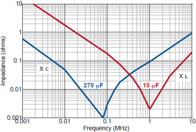
The answer is the DC link capacitors. In this case, the DC link capacitors are a few 220 μF electrolytic capacitors in parallel. Electrolytic capacitors (depending on types and manufacturers) often have a self resonant frequency at about 100 kHz. Some well-made electrolytic capacitors can have a much higher resonant frequency point. This means, the impedance of the capacitors is a lot higher at 5 kHz compared with 100 kHz. See diagram below. Checking the data sheet of the capacitors they use, the resonant frequency of the caps is indeed right at 100 kHz. This explains why the system has better immunity performance at 100 kHz.
Case 2: Expensive film caps fail to provide good differential filtering
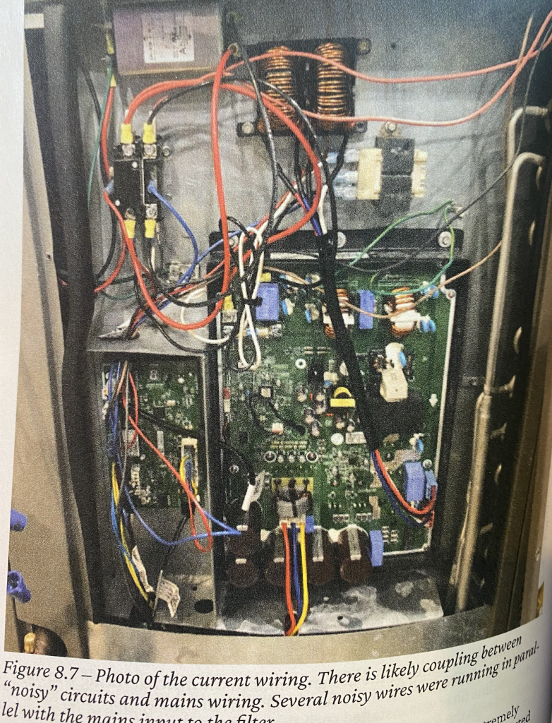
In this case, the client’s product is a 1 MVA voltage source inverter. The inverter uses a monster film cap as the DC link and the connection to the IGBTs are pretty much standard, i.e. laminated bus bars (plates) having short connection to the IGBT modules. The product failed terribly at both conducted and radiated emission tests. Looking inside their cabinet, all the cable routings are nice and tidy. Both DC and AC side cables have good distance (NOT like the one shown below in Figure 2). So it is very strange that the product failed the conducted emission quite badly. In fact, it is always a lot easier for EMC consultant to deal with a problem caused by the messy set up shown below. When you have a clean and tidy system, it is a lot harder to spot where the issues are.
The conducted emission failure is shown in Figure 3.
When seeing a conducted emission failure like this, it is often very important to determine whether the failure is more differential mode or common mode. At 150 kHz, it is clear that the noise should be dominated by differential noise rather than common mode noise. This is because capacitance to earth is always smaller than capacitance across DC. At low frequency, the small capacitance to earth for the common mode current is probably an order of magnitude or more lower than the different mode current.
So rather than trying to find a filter (which in this case is going to be big, heavy, bulky, expensive). The first step should be to check the differential mode noise. Good news is, the differential mode noise is very easy to measure. Just hook up an differential voltage probe on the DC bus bar, select AC coupled on the oscilloscope and measure the DC link ripple.
Once the DC link ripple is measured and confirmed to be excessive, then we can work out a plan to suppress the noise. The point we are trying to make here is you should pay more attention to the DC link capacitor.
In this article, we presented 2 case studies to demonstrate the importance of DC link capacitors and the role they play in power converter design. We will follow up the second case to update the readers with the new finding and how to design a proper power converter system.
Reference
[1] K. Wyatt, Workbench Troubleshooting EMC Emissions (Volume 2), https://www.amazon.com/Workbench-Troubleshooting-EMC-Emissions-Pre-Compliance/dp/B096YSZS7B/ref=sr_1_1?dchild=1&keywords=ken+Wyatt+emc&qid=1625476162&sr=8-1